REMOVAL
Removal / installation
| 1. DISCHARGE REFRIGERANT FROM REFRIGERATION SYSTEM |

Turn the A/C switch on.
Operate the A/C with the setting temperature at 25°C (77°F) and the blower level at LO for 10 minutes to circulate the refrigerant and collect compressor oil remaining in each component into the cooler compressor as much as possible.
Turn the ignition switch OFF.
Using SST, let the refrigerant gas out.
- SST
- 07110-58060
(07117-58080, 07117-58090, 07117-78050, 07117-88060, 07117-88070, 07117-88080)
| 2. DISCONNECT BATTERY NEGATIVE TERMINAL |
- CAUTION:
- Wait for 90 seconds after disconnecting the cable to prevent the airbag working.
| 3. REMOVE FRONT WIPER ARM AND BLADE ASSEMBLY RH |
Remove the 2 nuts and the front wiper arm and blade assembly RH.
| 4. REMOVE FRONT WIPER ARM AND BLADE ASSEMBLY LH |
Remove the nut and the front wiper arm and blade assembly LH.
| 5. REMOVE COWL TOP VENTILATOR LOUVER SUB-ASSEMBLY |
Remove the 2 clips.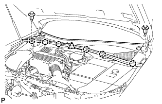

Disengage the 6 claws and the clamp, and remove the cowl top ventilator louver sub-assembly.
| 6. REMOVE WINDSHIELD WIPER LINK ASSEMBLY |
Disconnect the connector.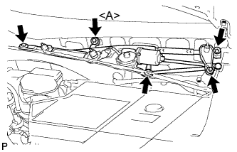
Remove the 5 bolts and the windshield wiper motor and link assembly.
- HINT:
- Bolt <A> cannot be removed because it is integrated into windshield wiper link assembly.
| 7. REMOVE COWL TOP PANEL OUTER SUB-ASSEMBLY |
Separate the wire harness clamp and grommet (A).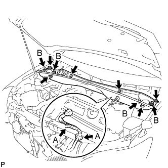
Remove the 4 shock absorber nuts (B).
Remove the 4 bolts, 2 nuts and cowl top panel sub-assembly.
Install the 4 shock absorber nuts.
- Torque:
- 80 N*m{ 815 kgf*cm , 59 ft.*lbf }
| 8. DISCONNECT AIR CONDITIONING TUBE AND ACCESSORY ASSEMBLY |
Install SST on the piping clamp.
- SST
- 09870-00025
- HINT:
- Make sure the direction of the piping clamp and SST by seeing the illustration shown on the caution label.
Push down SST and release the clamp lock.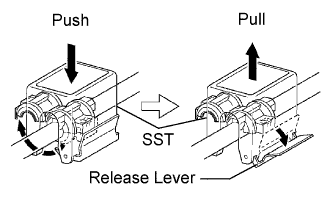
- NOTICE:
- Do not deform the tube when pushing the SST.
Pull the SST slightly and push the release lever, and then remove the piping clamp with SST.
Disconnect the air conditioning tube and accessory assembly.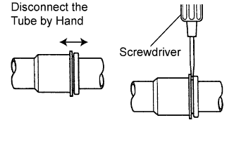
- NOTICE:
- Do not use tools like a screwdriver to remove the tube.
- Cap the open fittings immediately to keep moisture or dirt out of the system.
- Do not use tools like a screwdriver to remove the tube.
Remove the 2 O-rings from the air conditioning tube and accessory assembly.
| 9. DISCONNECT COOLER REFRIGERANT SUCTION HOSE NO.1 (LHD Type:) |
- SST
- 09870-00015
- HINT:
- Disconnection of the cooler refrigerant suction hose No.1 is the same as the air conditioning tube and accessory assembly.
| 10. DISCONNECT COOLER REFRIGERANT SUCTION PIPE NO.1 (RHD Type:) |
- SST
- 09870-00015
- HINT:
- Disconnection of the cooler refrigerant suction pipe No.1 is the same as the air conditioning tube and accessory assembly.
| 11. DISCONNECT HEATER WATER OUTLET HOSE |
Using pliers, grip the claws of the clip and slide the clip, and then disconnect the heater water outlet hose.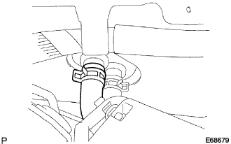
- NOTICE:
- Do not apply any excessive force to the heater water outlet hose.
- Prepare a drain pan or cloth for cooling water leaks.
- Do not apply any excessive force to the heater water outlet hose.
| 12. DISCONNECT HEATER WATER INLET HOSE |
- HINT:
- Disconnection of the heater water inlet hose is same as the heater water outlet hose.
| 13. REMOVE INSTRUMENT PANEL ASSEMBLY |
- HINT:
- Refer to the instructions for removal of the instrument panel assembly. (Click here)
| 14. REMOVE HYBRID VEHICLE CONTROL ECU |
Disconnect the 3 wire harness clamps.
Disconnect the 6 connectors from the hybrid vehicle control ECU.
Remove the 2 nuts and hybrid vehicle control ECU.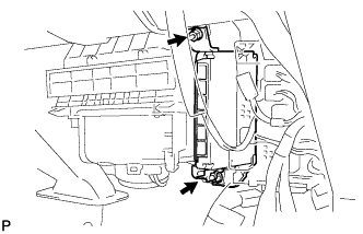
| 15. REMOVE AIR CONDITIONER AMPLIFIER ASSEMBLY |
Disconnect the connectors.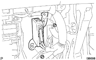
Remove the 2 nuts and air conditioner amplifier assembly.
| 16. REMOVE AIR DUCT REAR NO.2 |
Turn back the floor carpet.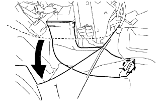
- HINT:
- Turn back the floor carpet so that the air duct rear No.2 can be removed.
Release the claw and remove the air duct rear No.2.
| 17. REMOVE AIR DUCT REAR NO.1 |
Turn back the floor carpet.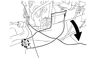
- HINT:
- Turn back the floor carpet so that the air duct rear No.1 can be removed.
Release the claw and remove the air duct rear No.1.
| 18. REMOVE AIR DUCT NO.1 |
Remove the bolt.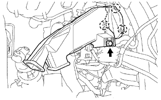
Release the 3 claws and remove the air duct No.1.
| 19. DISCONNECT TRANSMISSION CONTROL CABLE ASSEMBLY |
Using a screwdriver, disconnect the cable end from the shift lever assembly.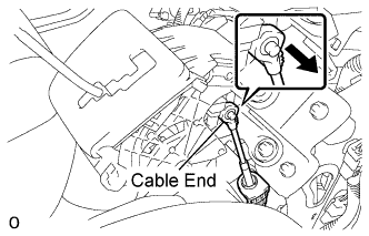
Pull out the stopper cap of the transmission control cable assembly.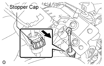
Turn the socket of the transmission control cable counterclockwise and remove the stopper cap.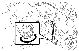
- NOTICE:
- Do not push in the stopper cap.
| 20. REMOVE SHIFT LEVER |
Disconnect the pattern select switch connector, the shift lock control computer connector and the indicator light wire connector.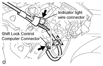
Remove the 4 nuts and disconnect the shift lever assembly from the vehicle.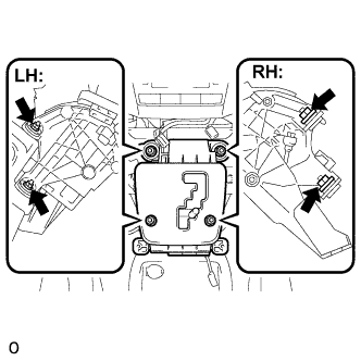
| 21. REMOVE INSTRUMENT PANEL BRACKET NO.4 |
Remove the 4 nuts and instrument panel bracket No.4.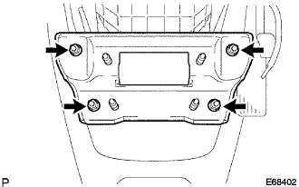
| 22. REMOVE INSTRUMENT PANEL BRACE NO.1 SUB-ASSEMBLY |
Remove the clamp and disconnect the connector.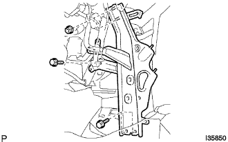
Remove the 3 bolts and 2 nuts and instrument panel brace No.1 sub-assembly.
| 23. REMOVE INSTRUMENT PANEL BRACE NO.2 SUB-ASSEMBLY |
Remove the clamp and disconnect the connector.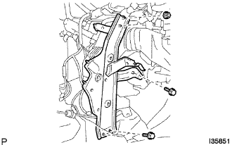
Remove the 3 bolts and 2 nuts and instrument panel brace No.2 sub-assembly.
| 24. SEPARATE STEERING INTERMEDIATE SHAFT SUB-ASSEMBLY (Manual Tilt Type) |
Loosen the bolt (A) and remove the clamp from the steering column hole shield.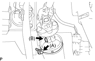
Loosen the bolt (B).
- HINT:
- Do not remove the bolt (B).
Remove the bolt, and then slide the steering intermediate shaft sub-assembly.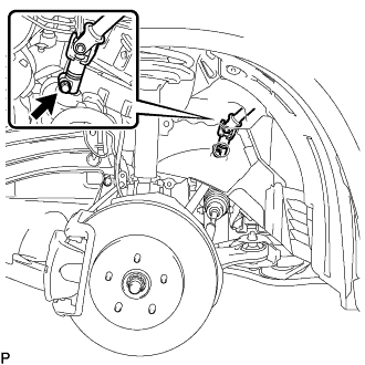
- NOTICE:
- Do not separate the steering intermediate shaft sub-assembly.
Put matchmarks on the steering intermediate shaft sub-assembly and the power steering link assembly.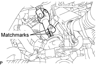
Separate the steering intermediate shaft sub-assembly from the power steering link assembly.
| 25. SEPARATE STEERING INTERMEDIATE SHAFT SUB-ASSEMBLY (Power Tilt and Power Type) |
Loosen the bolt (A) and remove the clamp from the steering column hole shield.
Loosen the bolt (B)
- HINT:
- Do not remove the bolt (B).
Remove the bolt, and then slide the steering intermediate shaft sub-assembly.
- NOTICE:
- Do not separate the steering intermediate shaft sub-assembly.
Put matchmarks on the steering intermediate shaft sub-assembly and the power steering link assembly.
Separate the steering intermediate shaft sub-assembly from the power steering link assembly.
| 26. REMOVE STEERING COLUMN ASSEMBLY (Manual Tilt Type) |
Disconnect the connectors and wire harness clamps from the steering column assembly.
Remove the 2 bolts, 2 nuts and the steering column assembly.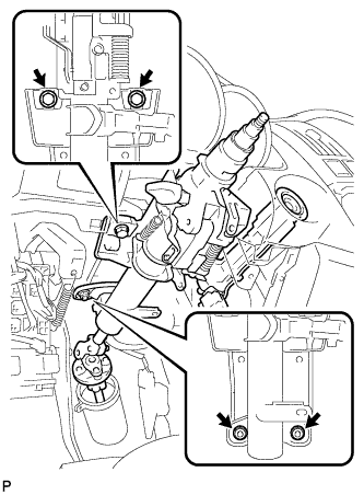
| 27. REMOVE STEERING COLUMN ASSEMBLY (Power Tilt and Power Type) |
Disconnect the connectors and wire harness clamps from the steering column assembly.
Remove the 2 bolts, 2 nuts and the steering column assembly.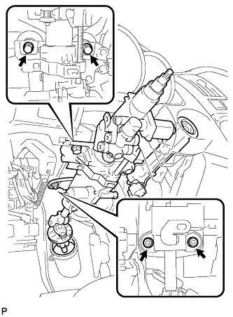
| 28. REMOVE AIR DUCT NO.1 SUB-ASSEMBLY |
Remove the 3 nuts and air duct No.1 sub-assembly.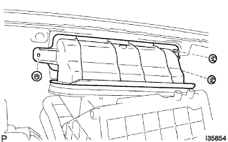
| 29. REMOVE INSTRUMENT PANEL REINFORCEMENT ASSEMBLY |
Remove the 4 bolts and 4 nuts.
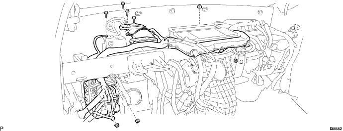
Remove the clamp.
Disconnect the connectors.
Remove the 9 bolts and the 2 nuts and then remove the instrument panel reinforcement while holding the air conditioner unit assembly.
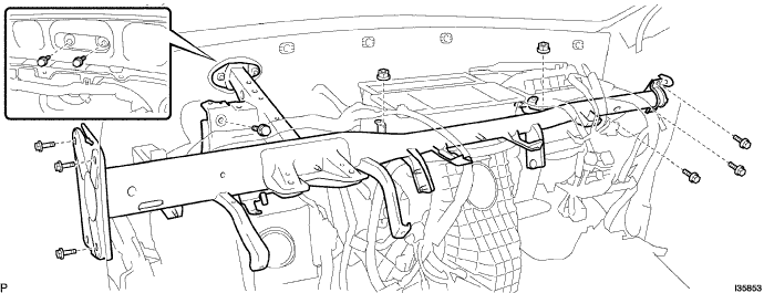
- HINT:
- Make sure to hold the air conditioner unit assembly securely as its bracket installation parts may be damaged.
| 30. REMOVE AIR CONDITIONER UNIT ASSEMBLY |
Remove the 2 nuts and air conditioner unit assembly.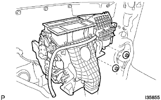
- HINT:
- Make sure to hold the air conditioner unit assembly securely as its bracket installation parts may be damaged.
| 31. REMOVE AIR DUCT NO.2 |
Remove the screw.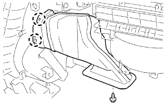
Release the 2 claws and remove the air duct No.2.
| 32. REMOVE WIRING AIR INDICATOR HARNESS NO.2 SUB-ASSEMBLY |
Remove the 3 screws.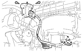
Remove the clamp and disconnect the 2 connectors.
Remove the wiring air indicator harness No.2 sub-assembly.
| 33. REMOVE BLOWER ASSEMBLY |
Remove the screw.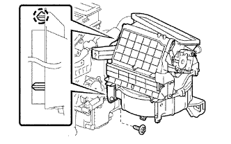
Release the claw and remove the blower assembly.