DTC P0560 / P0562 / P0563
Precautions: General safety (00)
DTC Detecting Condition and Trouble Area
| DTC detecting condition | Trouble area |
|---|---|
|
P0560: System Voltage Main power supply voltage is lower than 2.54 V for 10 sec. (3 D/C detection logic) |
•ECM power supply circuit and/or ground circuit
•Charging system •ECM |
|
P0562: System Voltage Low Main power supply circuit voltage is between 2.54 V and 9.8 V for 10 sec. with engine running. (3 D/C detection logic) |
|
|
P0563: System Voltage High Main power supply circuit voltage is higher than 16.5 V for 10 sec. with engine running. (3 D/C detection logic) |
Circuit Diagram
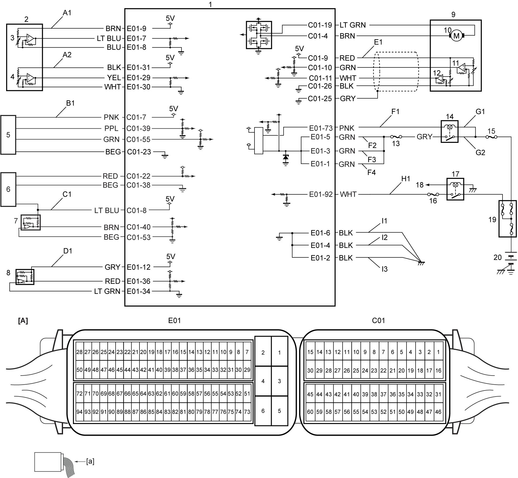
| [A]: | ECM connector (View: [a]) | H1: | Ignition signal circuit | 10. | Throttle actuator |
| A1: | APP sensor (main) power supply circuit | I1: | ECM ground circuit 1 | 11. | TP sensor (main) |
| A2: | APP sensor (sub) power supply circuit | I2: | ECM ground circuit 2 | 12. | TP sensor (sub) |
| B1: | Boost pressure sensor with IAT sensor-2 power supply circuit | I3: | ECM ground circuit 3 | 13. | “INJ DRV” fuse |
| C1: | Fuel pressure sensor and MAP sensor power supply circuit | 1. | ECM | 14. | Main relay |
| D1: | A/C refrigerant pressure sensor power supply circuit | 2. | APP sensor | 15. | “FI MAIN” fuse |
| E1: | TP sensor power supply circuit | 3. | APP sensor (main) | 16. | “IG COIL” fuse |
| F1: | Main relay drive circuit | 4. | APP sensor (sub) | 17. | IG1 relay |
| F2: | Main power supply circuit 1 | 5. | Boost pressure sensor with IAT sensor-2 | 18. | To keyless start control module |
| F3: | Main power supply circuit 2 | 6. | Fuel pressure sensor | 19. | Main fuse box |
| F4: | Main power supply circuit 3 | 7. | MAP sensor | 20. | Battery |
| G1: | Main relay power supply circuit (coil side) | 8. | A/C refrigerant pressure sensor | ||
| G2: | Main relay power supply circuit (switch side) | 9. | Electric throttle body assembly |
DTC Confirmation Procedure
P0560
1)Set ignition “ON” for 1 min.
P0562 / P0563
1)Run engine at idle speed for 1 min.
DTC Troubleshooting
| Step | Action | Yes | No |
|---|---|---|---|
| 1 |
Was “Engine and Emission Control System Check” performed?
|
Go to Step 2.
|
|
| 2 |
ECM power supply and ground circuit check
1)Check ECM power supply and ground circuits.

Is check result OK?
|
Go to Step 3.
|
Repair ECM power supply and/or ground circuit.
|
| 3 |
Charging system check
1)Check that charging system is working properly.
Is check result OK?
|
Replace ECM and recheck DTC.
|
Repair or replace defective parts.
|