DTC P0A5A
Precautions: General safety (00)
DTC Detecting Condition and Trouble Area
| DTC detecting condition | Trouble area |
|---|---|
|
P0A5A: Generator Current Sensor Circuit Range / Performance Any of the following conditions is met.
•Output voltage of electric load current sensor signal circuit is more than specified value. (1 D/C detection logic but MIL does not light up)•Output voltage of electric load current sensor signal circuit is lower than specified value. •Output voltage of electric load current sensor signal circuit is out of specified range. |
•Electric load current sensor and/or its circuit
•ECM •ENG A-STOP control module (ENG A-STOP model) |
Circuit Diagram
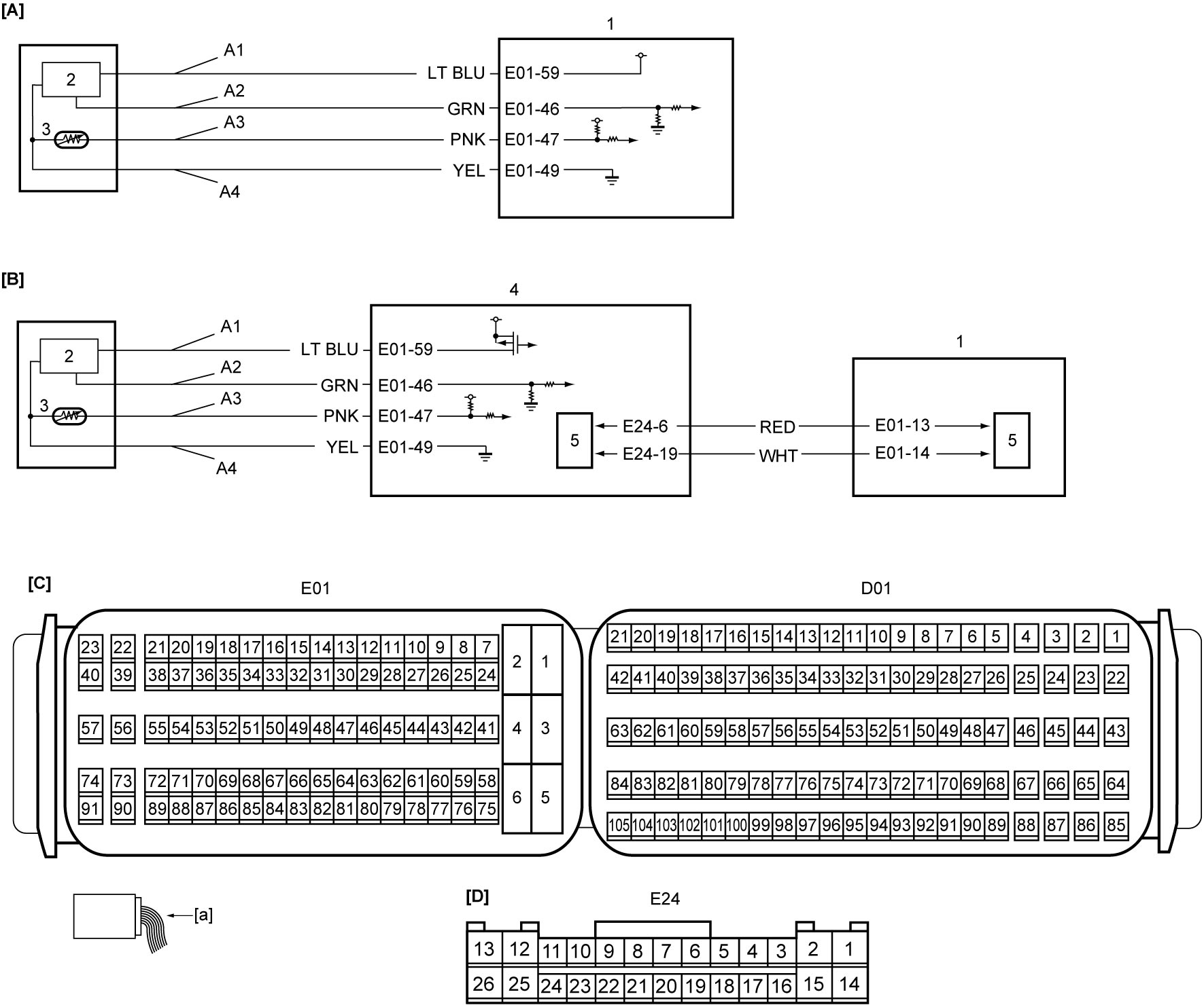
| [A]: | Non-ENG A-STOP model | A2: | Electric load current sensor signal circuit | 3. | Battery temperature sensor |
| [B]: | ENG A-STOP model | A3: | Battery temperature sensor signal circuit | 4. | ENG A-STOP control module |
| [C]: | ECM connector (View: [a]) | A4: | Electric load current sensor ground circuit | 5. | CAN driver |
| [D]: | ENG A-STOP control module connector (View: [a]) | 1. | ECM | ||
| A1: | Electric load current sensor power supply circuit | 2. | Electric load current sensor |
DTC Confirmation Procedure
1)Run engine at idle speed for 1 min.
DTC Troubleshooting
| Step | Action | Yes | No |
|---|---|---|---|
| 1 |
Was “Engine and Emission Control System Check” performed?
|
Non-ENG A-STOP model: Go to Step 2.
ENG A-STOP model: Go to Step 5.
|
|
| 2 |
Electric load current sensor power supply circuit check
1)With ignition is “OFF”, disconnect electric load current sensor connector.
2)Check for proper terminal connection to electric load current sensor connector.
3)If connections are OK, set ignition “ON”.
4)Check that voltage between “A1” and “A4” is approx. 5 V.
Is check result OK?
|
Go to Step 4.
|
Go to Step 3.
|
| 3 |
Electric load current sensor ground circuit check
1)Check that voltage between “A1” and ground is approx. 5 V.
Is check result OK?
|
Repair “A4” circuit.
If this DTC is detected again, replace ECM and recheck DTC.

|
Repair “A1” circuit.
If this DTC is detected again, replace ECM and recheck DTC.
|
| 4 |
Electric load current sensor signal circuit check
1)With ignition is “OFF”, disconnect “E01” connector from ECM.
2)Check for proper terminal connection to “E01” connector.
3)If connections are OK, check the following points.
•Resistance of “A2” circuit: less than 1 Ω
•Resistance between “A2” circuit and ground: infinity •Resistance between “A2” circuit terminal and other terminal at electric load current sensor connector: infinity •Voltage of “A2” circuit: approx. 0 V (When ignition is “ON”) Is check result OK?
|
Go to Step 8.
|
Repair or replace defective wire harness.
|
| 5 |
DTC check
1)Check DTC in ENG A-STOP control module.
Is DTC P1321 or P1322 detected?
|
Go to troubleshooting in DTC P1321 / P1322.
|
Go to Step 6.
|
| 6 |
DTC check
Is there any DTC other than P1321 or P1322 detected?
|
Go to troubleshooting for detected DTC.
|
Go to Step 7.
|
| 7 |
Electric load current sensor power supply circuit, signal circuit and ground circuit check
1)Check “A1”, “A2” and “A4” circuits between electric load current sensor and ENG A-STOP control module according to Step 1 – 4 of DTC P1321 / P1322.
Is check result OK?
|
Go to Step 8.
|
Repair or replace defective wire harness.
|
| 8 |
Electric load current sensor check
1)Check electric load current sensor.
Is check result OK?
|
Replace ECM and recheck DTC.
|
Replace electric load current sensor.
|