Valve Clearance Inspection and Adjustment
Precautions: General safety (00)
Inspection
1)Disconnect negative (–) cable at battery.
2)Remove cylinder head cover. 
3)Hoist vehicle and remove engine undercover.
4)Using wrench, turn crankshaft pulley (1) clockwise until cam lobes (2) become perpendicular to shim faces (3) at valves “1” and “7” as shown in figure.
5)Check valve clearance with feeler gauge (4) as follows.
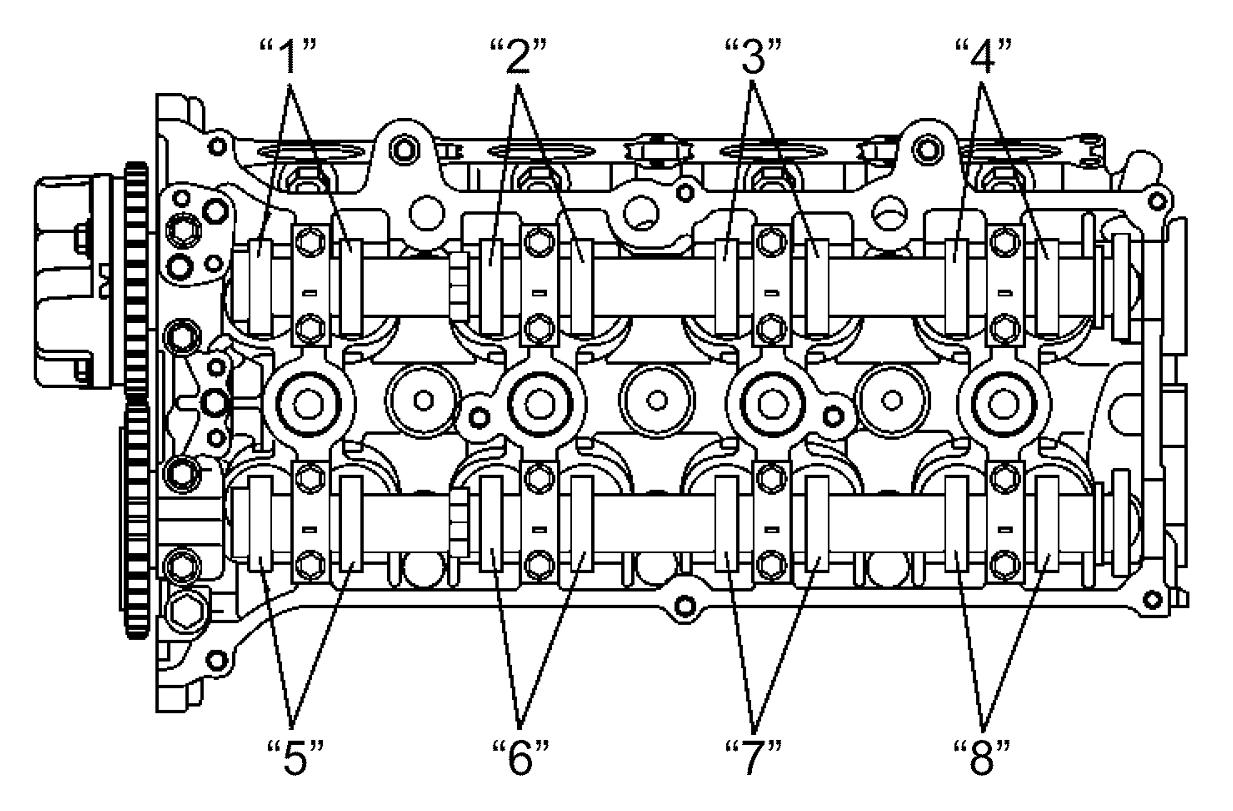
a)Check valve clearance at valves “1” and “7”.
b)Turn camshafts by 90° (by turning crankshaft with wrench).
c)Check that cam lobes are perpendicular to shim faces at valves to be checked (in this case, “3” and “8”). If not, adjust cam lob position by turning crankshaft. Check valve clearances.
d)In the same manner as in Step b) – c), check valve clearances at valves “4” and “6”.
e)In the same manner as in Step b) – c) again, check valve clearances at valves “2” and “5”.
If valve clearance is not as specified, record valve clearance and adjust it to specification.
Valve clearance specification
When cold (ECT: 15 – 25 °C (59 – 77 °F)):
•Intake:
0.18 – 0.22 mm (0.0071 – 0.0086 in.)
•Exhaust:
0.28 – 0.32 mm (0.0111 – 0.0125 in.)

| “a”: | 90° |
Adjustment
1)Close the valve whose shim (2) is to be replaced by turning crankshaft, and then turn tappet (3) till its cut section (1) faces inside as shown in figure.
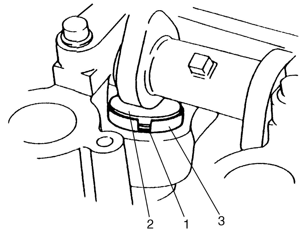

2)Lift down the valve by turning crankshaft 360°.
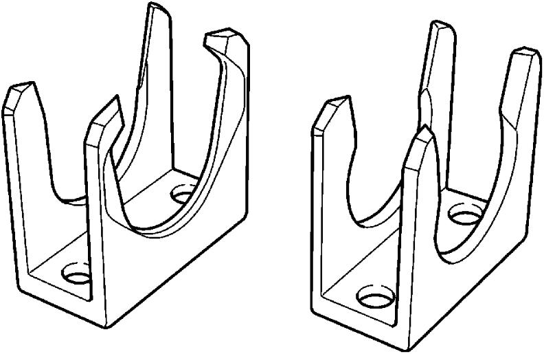
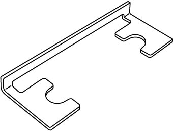
3)Hold tappet at that position using special tool as follows.
a)Remove its housing bolts.
b)Check housing No. and select special tool corresponding to housing No., referring to “Special tool selection table”.
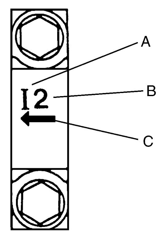
Special tool selection table
| No. on camshaft housing | Embossed mark on special tool |
|---|---|
| I2 | IN2 |
| I3, I4, I5 | IN345 |
| E2 | EX2 |
| E3, E4, E5 | EX345 |
| A: | I: Intake side or E: Exhaust side |
| B: | Position from timing chain side |
| C: | Pointing the timing chain side |
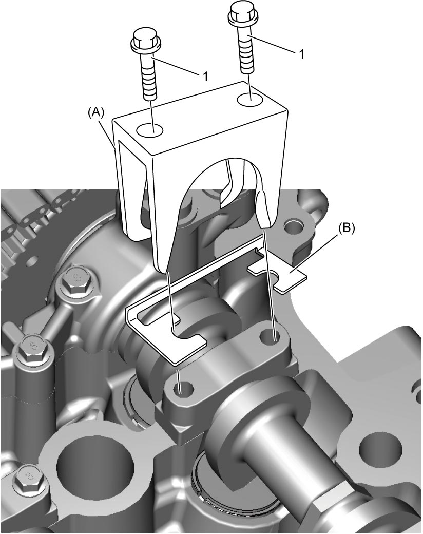
c)Hold down the tappet so as not to contact the shim by installing special tools on camshaft housing with housing bolts (1) as shown in figure and tightening housing bolts by hand.
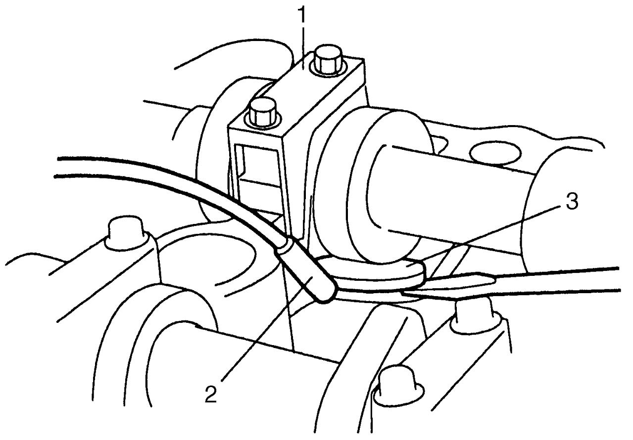
4)Turn cam-lobes approximately 90° clockwise by turning crankshaft and remove shim (3) using magnet (2).
| 1. | Special tool |
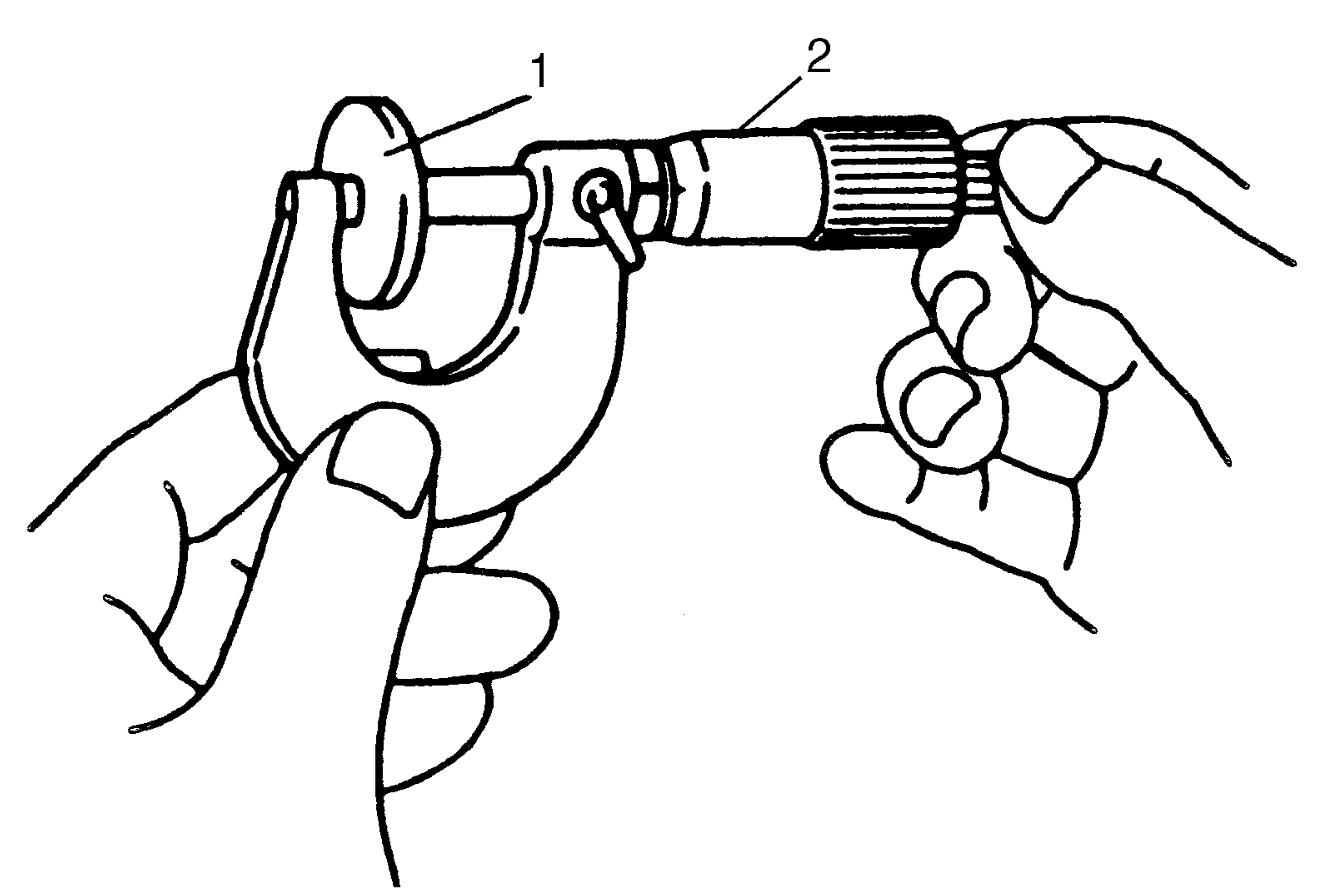
5)Using a micrometer (2), measure the thickness of the removed shim (1), and determine replacement shim by calculating the thickness of new shim with the following formula and table.
 Example of intake side:
When thickness of removed shim is 2.40 mm (0.094 in.), measured valve clearance is 0.45 mm (0.018 in.).
A = 2.40 mm (0.094 in.) + 0.45 mm (0.018 in.) – 0.20 mm (0.008 in.) = 2.65 mm (0.104 in.)
Calculated thickness of new shim = 2.65 mm (0.104 in.)
Shim thickness specification
Intake side:
A = B + C – 0.20 mm (0.008 in.)
Exhaust side:
A = B + C – 0.30 mm (0.012 in.)
A: Thickness of new shim
B: Thickness of removed shim
C: Measured valve clearance
When thickness of removed shim is 2.40 mm (0.094 in.), measured valve clearance is 0.45 mm (0.018 in.).
A = 2.40 mm (0.094 in.) + 0.45 mm (0.018 in.) – 0.20 mm (0.008 in.) = 2.65 mm (0.104 in.)
Calculated thickness of new shim = 2.65 mm (0.104 in.)
6)Select new shim No. (1) with a thickness as close as possible to calculated value.
![img]()
Available shims No.
| Thickness mm (in.) | Shim No. | Thickness mm (in.) | Shim No. |
|---|---|---|---|
| 2.175 (0.0856) | 218 | 2.600 (0.1024) | 260 |
| 2.200 (0.0866) | 220 | 2.625 (0.1033) | 263 |
| 2.225 (0.0876) | 223 | 2.650 (0.1043) | 265 |
| 2.250 (0.0886) | 225 | 2.675 (0.1053) | 268 |
| 2.275 (0.0896) | 228 | 2.700 (0.1063) | 270 |
| 2.300 (0.0906) | 230 | 2.725 (0.1073) | 273 |
| 2.325 (0.0915) | 233 | 2.750 (0.1083) | 275 |
| 2.350 (0.0925) | 235 | 2.775 (0.1093) | 278 |
| 2.375 (0.0935) | 238 | 2.800 (0.1102) | 280 |
| 2.400 (0.0945) | 240 | 2.825 (0.1112) | 283 |
| 2.425 (0.0955) | 243 | 2.850 (0.1122) | 285 |
| 2.450 (0.0965) | 245 | 2.875 (0.1132) | 288 |
| 2.475 (0.0974) | 248 | 2.900 (0.1142) | 290 |
| 2.500 (0.0984) | 250 | 2.925 (0.1152) | 293 |
| 2.525 (0.0994) | 253 | 2.950 (0.1161) | 295 |
| 2.550 (0.1004) | 255 | 2.975 (0.1171) | 298 |
| 2.575 (0.1014) | 258 | 3.000 (0.1181) | 300 |
7)Install new shim on tappet using special tool.
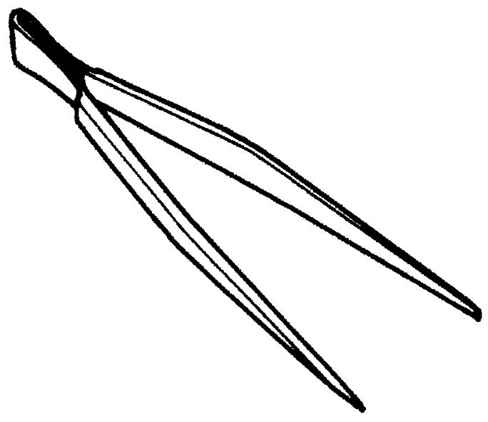
8)Lift valve by turning crankshaft counterclockwise (in opposite direction against above Step 4)) and remove special tools.
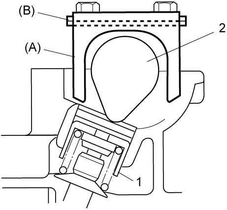
| 1. | Tappet | 2. | Camshaft |
9)Install camshaft housing bolts.
10)Recheck valve clearance.
11)Install engine undercover.
12)Install cylinder head cover.
13)Connect negative (–) cable at battery.