Compression Check
Precautions: General safety (00)
1)Warm up engine to normal operating temperature.
2)Stop engine after warming up.
3)For M/T model, place gear shift lever in “Neutral” and apply parking brake.
For A/T model, place select lever in “P” and apply parking brake.
For A/T model, place select lever in “P” and apply parking brake.
4)Remove air cleaner assembly. 
5)Remove all ignition coil assemblies and all spark plugs.
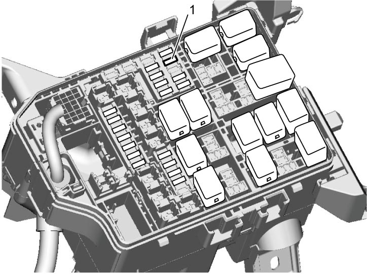
6)Remove individual circuit fuse box No.1 cover.
7)Remove “INJ DRV” fuse (1) so that ignition and injection signals come to stop.

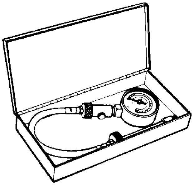
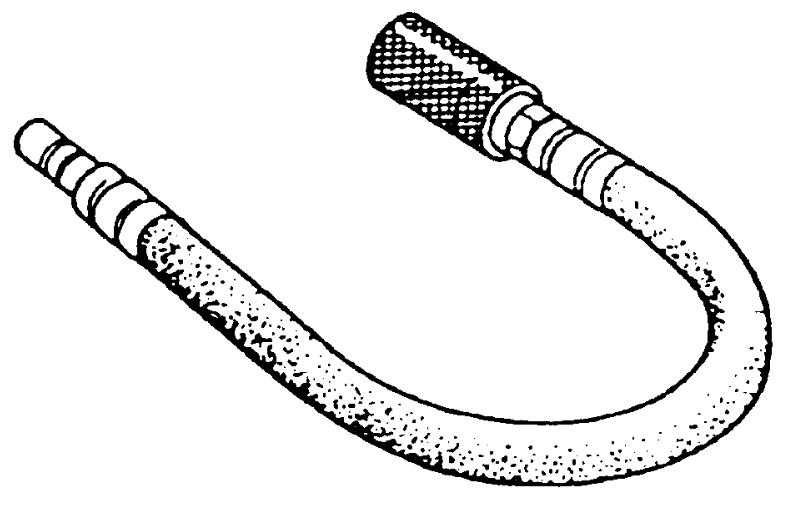
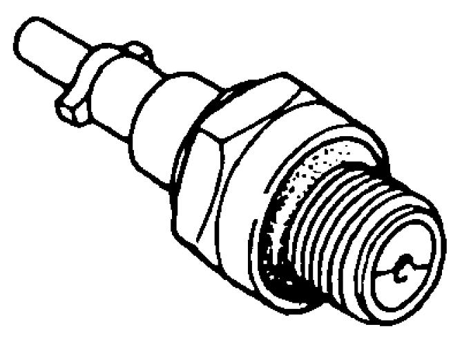
8)Install special tools into spark plug hole.
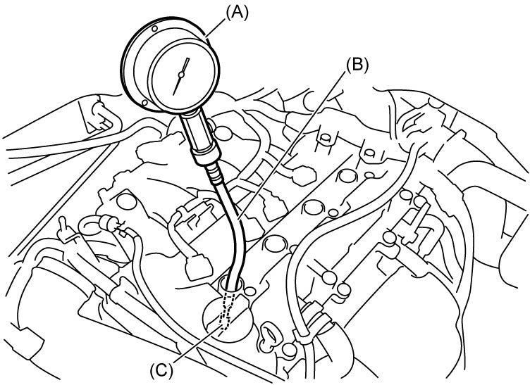
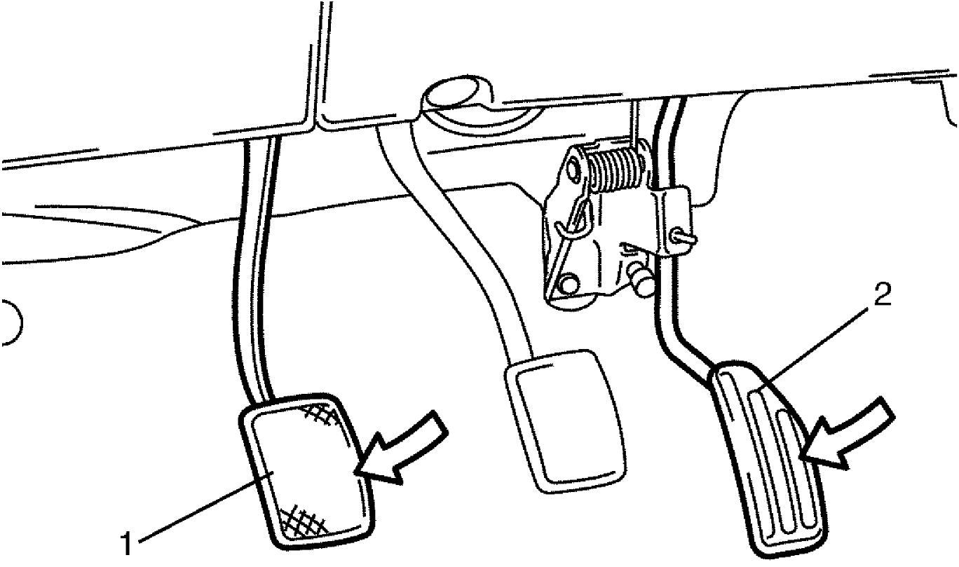
9)Disengage clutch (1) (to lighten starting load on engine) for M/T model, and depress accelerator pedal (2) all the way to make throttle fully open.
10)Crank engine with fully charged battery, and read the highest pressure on special tool.
NOTE:
•For measuring compression pressure, crank engine at least 200 rpm with fully charged battery.
•Check installation condition of special tool if measured compression pressure is lower than the limit.
•If the measured compression pressure of particular cylinder is lower than the limit, add a bit of engine oil into the cylinder through the spark plug hole, and then repeat the compression check.
•Check installation condition of special tool if measured compression pressure is lower than the limit.
•If the measured compression pressure of particular cylinder is lower than the limit, add a bit of engine oil into the cylinder through the spark plug hole, and then repeat the compression check.
—If the compression pressure increases after adding engine oil, the following may be the cause:
—Pressure leakage due to worn piston rings or worn cylinder
—If the compression pressure does not increase, one of the following may be the cause:
—Incorrect valve timing
—Pressure leakage from the valve or valve seats
—Pressure leakage from the cylinder head gasket
—Pressure leakage from the valve or valve seats
—Pressure leakage from the cylinder head gasket
Compression pressure
Standard: 1,500 kPa (15.2 kgf/cm2, 217 psi, 15 bar)
Limit: 1,200 kPa (12.2 kgf/cm2, 174 psi, 12 bar)
Max. difference between any two cylinders: 100 kPa (1.0 kgf/cm2, 14.5 psi, 1 bar)
11)Carry out Step 8) – 10) on each cylinder to obtain 4 readings.
12)Install spark plugs and ignition coil assemblies.
13)Install “FI” fuse.
14)Install individual circuit fuse box No.1 cover.
15)Install air cleaner assembly.