DPF® Removal and Installation
Precautions: General safety (00)
NOTICE:
Applying a shock to the DPF® may cause damage to the ceramic monolith inside.
Handle the DPF® carefully. Be careful not to drop it or hit it against something.
NOTE:
When replacing DPF®, initialize DPF® data in ECM. 
Removal
1)Disconnect negative (–) cable at battery.
2)Remove engine cover.
3)Remove exhaust manifold upper cover (1).
4)Remove A/F sensor-1 (2), if necessary.
5)Remove EGT sensor-1 (3), if necessary.
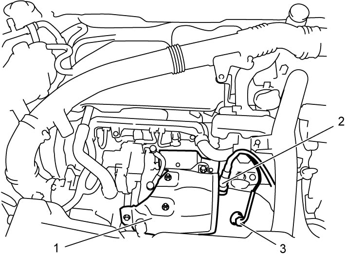

6)Remove differential pressure sensor hoses (1).
7)Hoist vehicle and remove engine undercover.
8)Remove A/F sensor-2 (2), if necessary.
9)Remove EGT sensor-2 (3) and -3 (4), if necessary.
10)Remove EGR lower pipe (5).
11)Remove DPF® clamp (6).
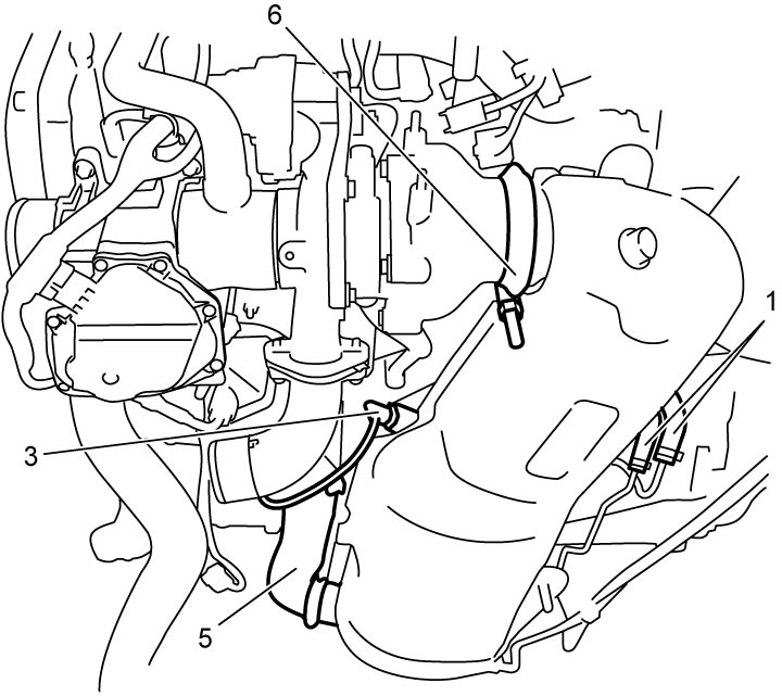
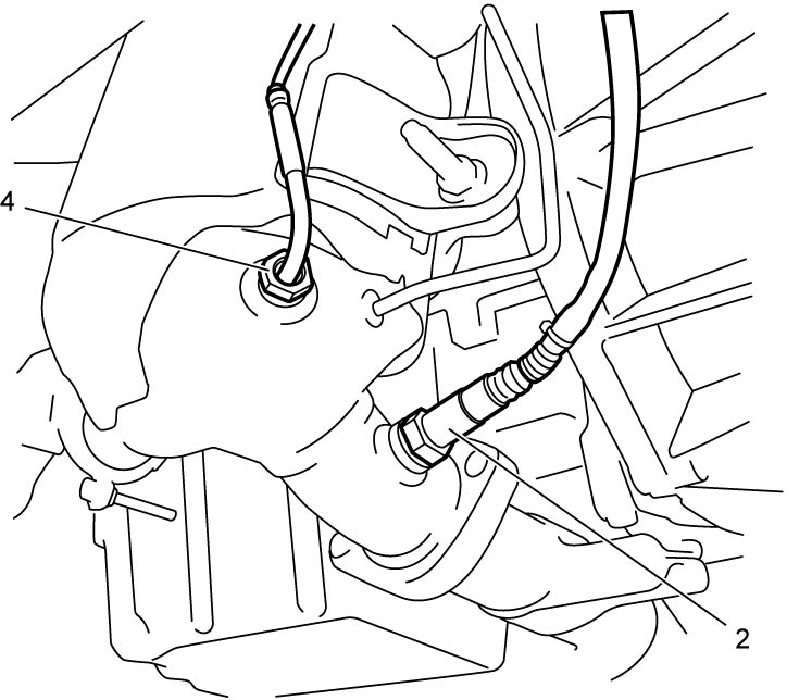
12)Remove exhaust No.1 pipe nuts and exhaust No.1 pipe brace bolt.
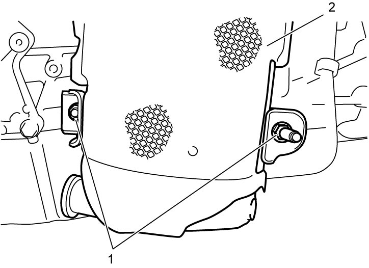
13)Remove DPF® bracket nuts (1) and remove DPF® (2) downward.
Installation
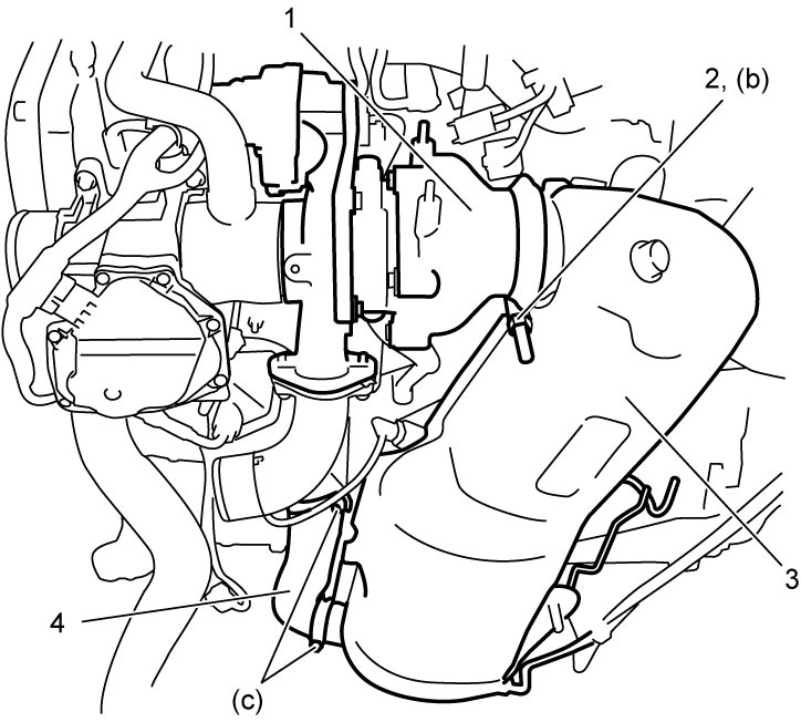
1)Install DPF® (3) as follows.
a)Connect turbocharger (1) and DPF® properly, and temporarily tighten DPF® clamp (2) to 5.0 N·m (0.51 kgf-m, 4.0 lbf-ft).
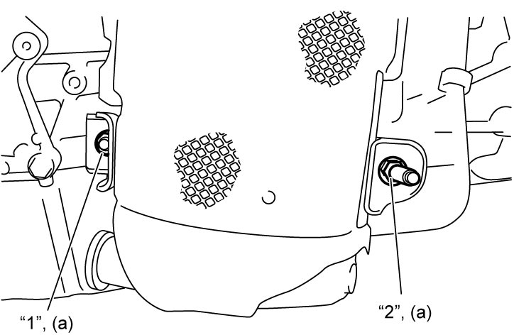
b)Temporarily tighten DPF® bracket nuts in numerical order (“1” – “2”) to 5.0 N·m (0.51 kgf-m, 4.0 lbf-ft).
c)Connect EGR lower pipe (4) to DPF® and EGR cooler properly, and temporarily tighten EGR lower pipe clamps by hand.
d)Tighten EGR lower pipe clamps to 9.0 N·m (0.92 kgf-m, 7.0 lbf-ft).
e)Retighten EGR lower pipe clamps to 11 N·m (1.1 kgf-m, 8.5 lbf-ft).
f)Tighten DPF® clamp to 25 N·m (2.5 kgf-m, 18.5 lbf-ft).
g)Tighten DPF® bracket nuts in numerical order (“1” – “2”) to 25 N·m (2.5 kgf-m, 18.5 lbf-ft).
h)Tighten exhaust No.1 pipe brace bolt and tighten exhaust No.1 pipe nuts to specified torque.
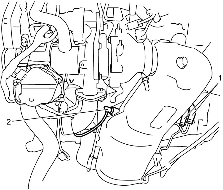
2)Connect differential pressure sensor hoses (1).
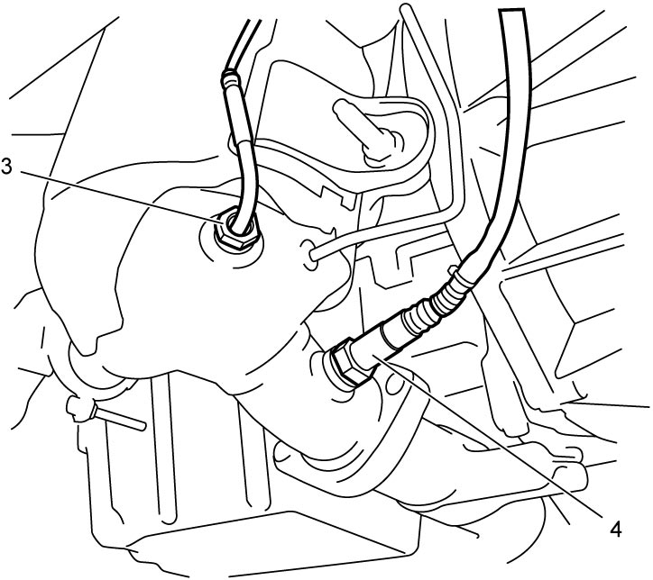
3)Install EGT sensor-2 (2) and -3 (3), if removed.
4)Install A/F sensor-2 (4), if removed.
5)Install engine undercover.
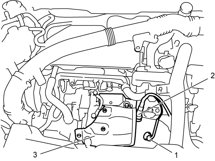
6)Install EGT sensor-1 (1), if removed.
7)Install A/F sensor-1 (2), if removed.
8)Install exhaust manifold upper cover (3).
9)Install engine cover.
10)Connect negative (–) cable at battery.
11)Start engine and check each joint of exhaust system for exhaust gas leakage.
12)When replacing new DPF®, initialize DPF® parameter in ECM.