Front Wheel Hub, Steering Knuckle and Wheel Bearing Removal and Installation
Precautions: General safety (00)
Removal
1)Hoist vehicle and remove front wheel.
2)Release caulking from drive shaft nut (1) and remove drive shaft nut with brake pedal depressed.
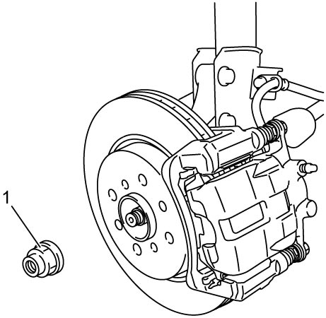

3)Remove front brake disc. 
4)Disconnect front wheel speed sensor from steering knuckle.
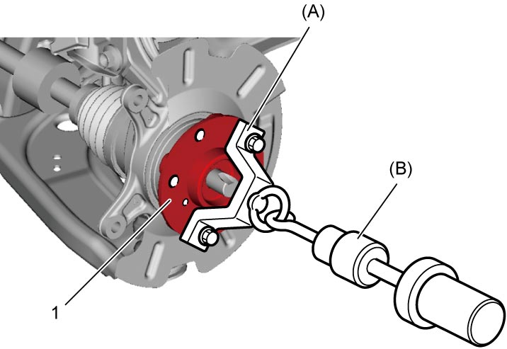
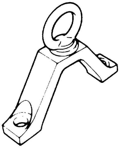
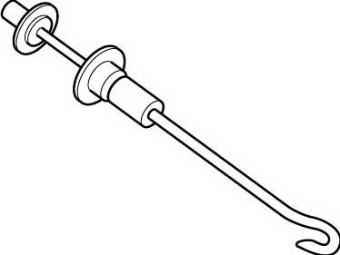
5)Pull out wheel hub (1) with special tools.
NOTE:
Outer side of wheel bearing inner race comes out together with wheel hub.
6)Disconnect tie-rod end from steering knuckle.
7)Disconnect suspension arm joint from steering knuckle.
8)Remove strut bracket nuts and bolts.
9)Remove steering knuckle from drive shaft.
10)Remove front brake dust cover (1) after releasing caulking with chisel or the like.
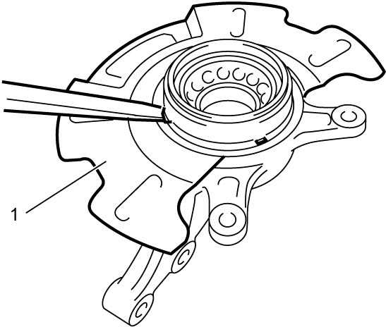
11)Remove circlip (1) from steering knuckle.
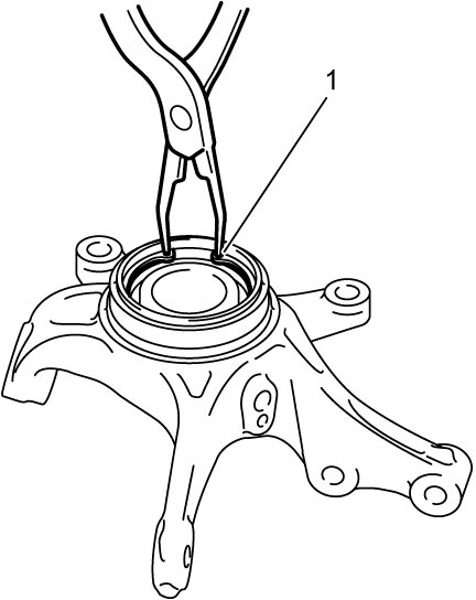
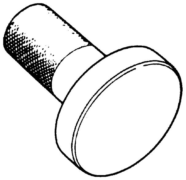
12)Using hydraulic press (1) and special tools, push out wheel bearing.
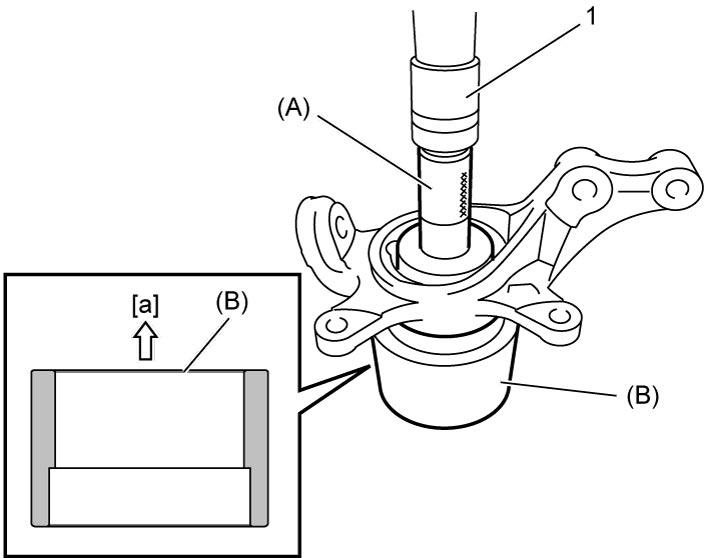
| [a]: | Steering knuckle side |
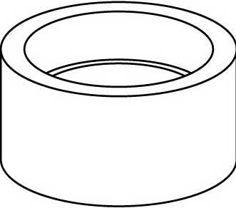
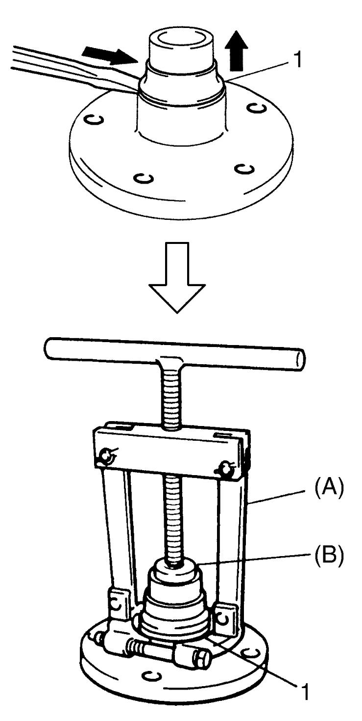
13)Pry wheel bearing outside inner race (1) a little using chisel or the like.
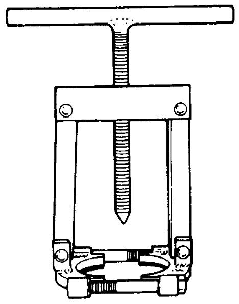
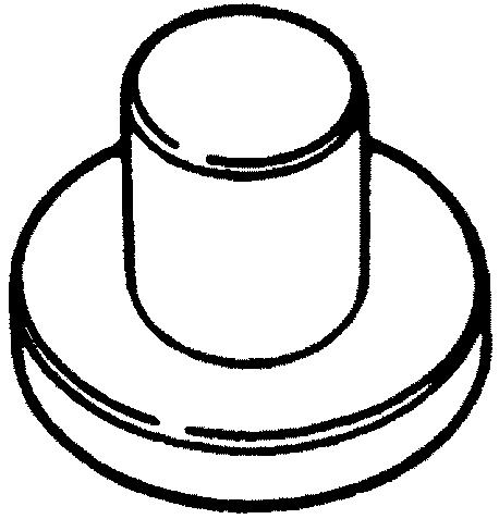
14)Remove wheel bearing outside inner race (1) from wheel hub using special tools as shown in figure.
Installation
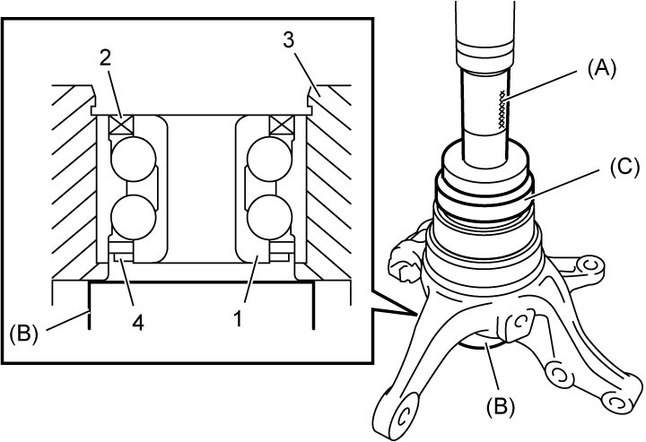
1)Put new wheel bearing (1) on steering knuckle (3) with its black rubber grooved seal (2) toward wheel and dark-brown magnetic encoder seal (4) toward drive shaft, i.e., facing down dark-brown magnetic encoder seal (4) as shown in figure.
NOTICE:
•If the wheel hub is removed and reinstalled without replacing the wheel bearing with a new one, the wheel bearing may not operate properly.
Whenever the wheel hub is removed, replace the wheel bearing with a new one.
•The dark-brown magnetic encoder seal should face the drive shaft side for the front wheel speed sensor. The incorrect installation of the wheel bearing will cause a malfunction of the wheel speed sensing function. Install the wheel bearing in the specified direction.
Whenever the wheel hub is removed, replace the wheel bearing with a new one.
•The dark-brown magnetic encoder seal should face the drive shaft side for the front wheel speed sensor. The incorrect installation of the wheel bearing will cause a malfunction of the wheel speed sensing function. Install the wheel bearing in the specified direction.
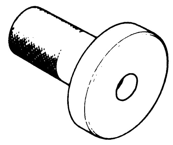
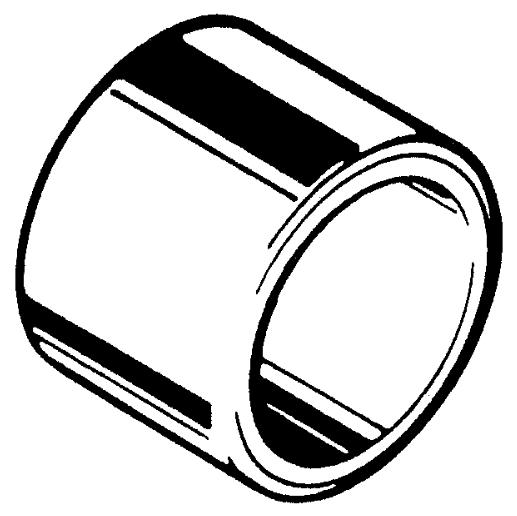
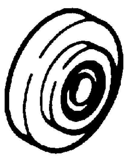
2)Press-fit wheel bearing into steering knuckle (3) using special tools as shown in figure.
3)Install new circlip (1).
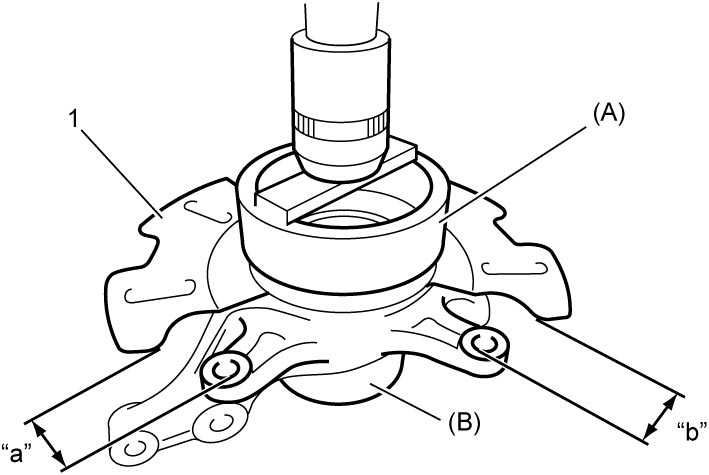
4)Press-fit new front brake dust cover (1) to steering knuckle using hydraulic press and special tools so that dimensions “a” and “b” become equal as shown in figure.
NOTICE:
If the dust cover is reused, the dust cover can come off and damage the brake system.
Install new dust cover.
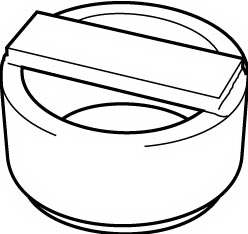
5)Caulk more than 4 points with a small cold chisel.
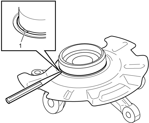
| 1. | Caulking |
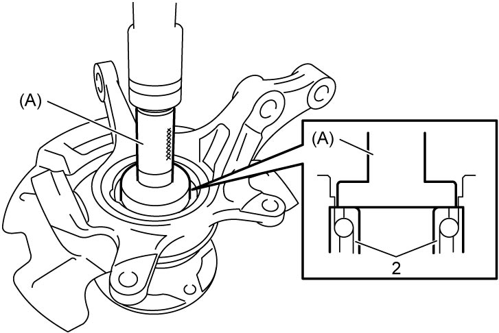
6)Using special tool and hydraulic press, press-fit wheel hub (1) into wheel bearing (2).
7)Apply grease lightly to end face of wheel bearing inner race (1).
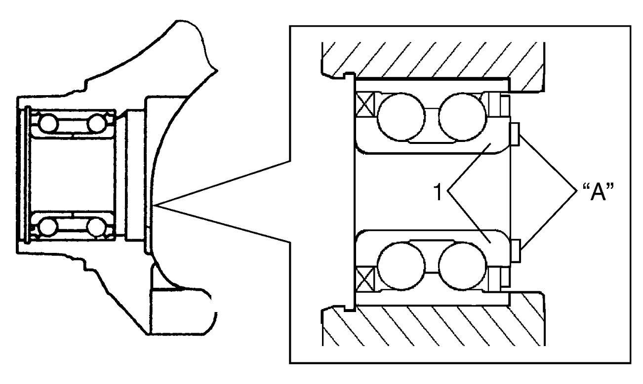
NOTE:
Do not apply the grease to the encoder section to avoid the encoder malfunction.
8)Install steering knuckle to drive shaft.
9)Install strut bracket bolts and nuts.
10)Connect steering knuckle to suspension arm.
11)Connect tie-rod end to steering knuckle.
12)Install front wheel speed sensor.
13)Install brake disc and brake caliper.
14)Tighten new drive shaft nut to specified torque.
15)Check front wheel alignment.