DTC C1016
Precautions: Precautions for ESP® · Precautions for Diagnosing Trouble · Test with Speedometer Tester or Other Equipment · Precautions for Brakes · General safety (00)
DTC Detecting Condition and Trouble Area
| DTC detecting condition | Trouble area |
|---|---|
|
C1016: Brake Light Switch Circuit Performance
•Brake light switch ON signal is detected for more than specified time while vehicle running with accelerator pedal depressed.
•Brake light switch ON signal is not detected although master cylinder pressure sensor signal is more than specified value. |
•Brake light switch circuit
•Brake light switch •ECM •ESP® control module |
Circuit Diagram
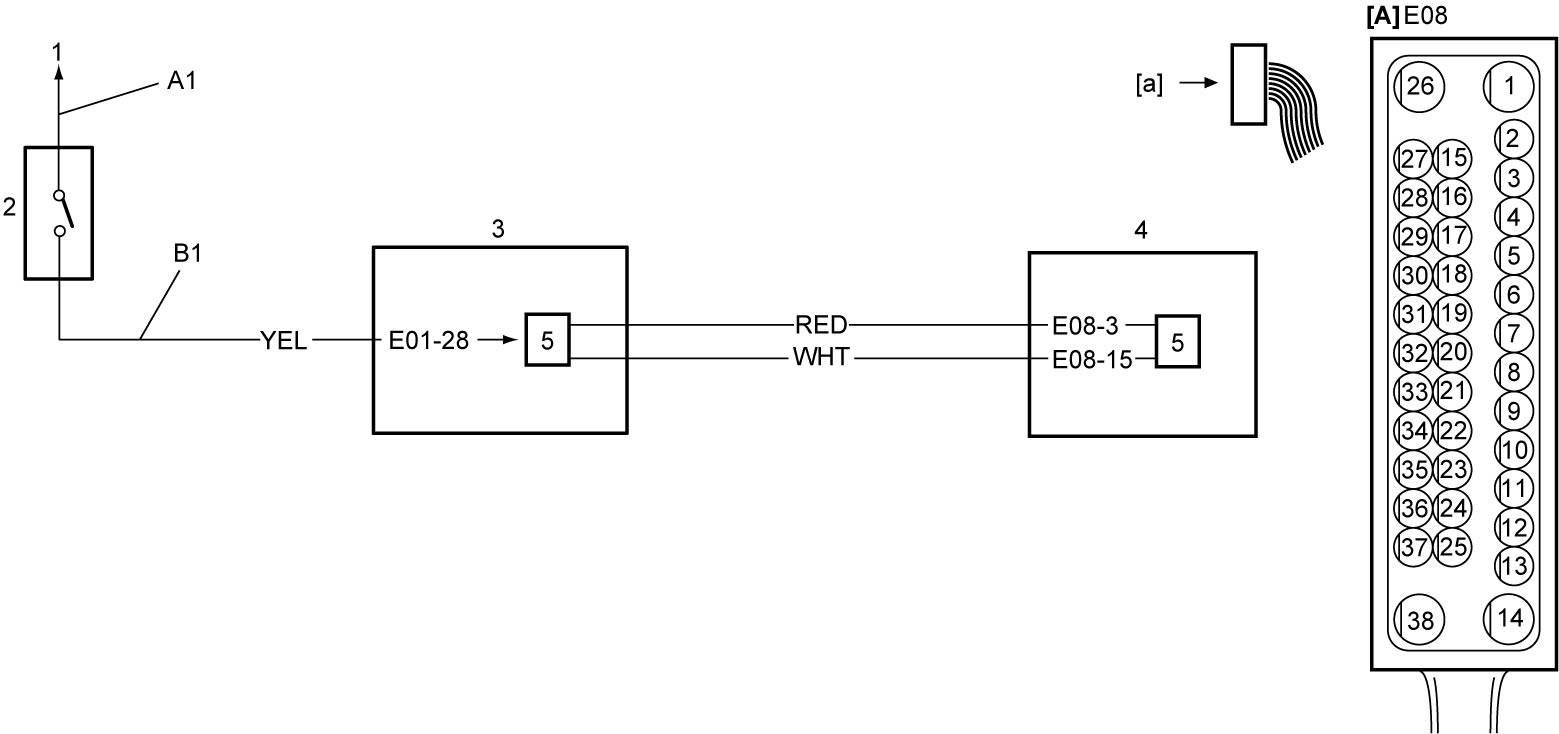
| [A]: | ESP® control module connector (View: [a]) | 1. | Lead to battery | 4. | ECM |
| A1: | Brake light switch power supply circuit | 2. | Brake light switch | 5. | ESP® control module |
| B1: | Brake light switch signal circuit | 3. | Brake light | 6. | CAN driver |
DTC Troubleshooting
| Step | Action | Yes | No |
|---|---|---|---|
| 1 |
Was “ESP® System Check” performed?
|
Go to Step 2.
|
Go to ESP® System Check.
|
| 2 |
DTC check
1)Perform DTC Check.
Is DTC U0073 and/or U0100 detected?
|
Go to applicable DTC troubleshooting.
|
Go to Step 3.
|
| 3 |
Brake light switch power supply circuit check
1)When ignition is “OFF”, disconnect brake light switch connector.
2)Check for proper connection to brake light switch connector.
3)If connections are OK, set ignition “ON”.
4)Check that voltage between “A1” circuit and ground is 10 – 14 V.
Is check result OK?
|
Go to Step 4.
|
Repair or replace defective wire harness.
|
| 4 |
Brake light switch signal circuit check
1)When ignition is “OFF”, disconnect connectors from ECM and brake light.
2)Check for proper connection to ECM connectors.
3)If connections are OK, check the following points.
•Resistance of “B1” circuit: less than 1 Ω
•Resistance between “B1” circuit and ground: infinity •Resistance between “B1” circuit terminal and other terminal at brake light switch connector: infinity •Voltage of “B1” circuit: approx. 0 V (When ignition is “ON”) Is check result OK?
|
Go to Step 5.
|
Repair or replace defective wire harness.
|
| 5 |
Brake light switch check
1)Check brake light switch.

Is check result OK?
|
Replace ESP® hydraulic unit / control module assembly and recheck DTC.
|
Repair brake light switch.
|