DTC C1021 / C1022 / C1025 / C1026 / C1031 / C1032 / C1033 / C1035 / C1036
Precautions: Precautions for ESP® · Precautions for Diagnosing Trouble · Test with Speedometer Tester or Other Equipment · Precautions for Brakes · General safety (00)
DTC Detecting Condition and Trouble Area
| DTC detecting condition | Trouble area |
|---|---|
|
C1021 / C1025 / C1031 / C1035: Right-Front / Left-Front / Right-Rear / Left-Rear Wheel Speed Sensor Circuit Voltage Wheel speed sensor signal is out of specified range. |
•Wheel speed sensor
•Wheel speed sensor circuit •Wheel speed sensor encoder •ESP® control module |
|
C1022 / C1026 / C1032 / C1036: Right-Front / Left-Front / Right-Rear / Left-Rear Wheel Speed Sensor or Encoder Signal Performance Abnormal wheel speed sensor signal is detected continuously. |
|
|
C1033: Wheel Speed Sensor Deviation
•Abnormal wheel speed sensor signal is detected continuously at two or more wheel speed sensors.
•ABS control is activated for more than specified time. •Wheel speed sensor driver power supply voltage is out of specified range. |
NOTE:
When vehicle was placed in any of the following conditions, one of these DTCs may be set although sensor is in good condition. If such possibility is suspected, clear DTC once  and check whether any abnormality exists or not by performing road test as described in Step 3 of ESP® System Check.
and check whether any abnormality exists or not by performing road test as described in Step 3 of ESP® System Check.
•Vehicle is driven with parking brake lever pulled.
•Wheel spins while driving.
•Wheel(s) is rotated while vehicle is jacked up.
•Wheel spins while driving.
•Wheel(s) is rotated while vehicle is jacked up.
Circuit Diagram
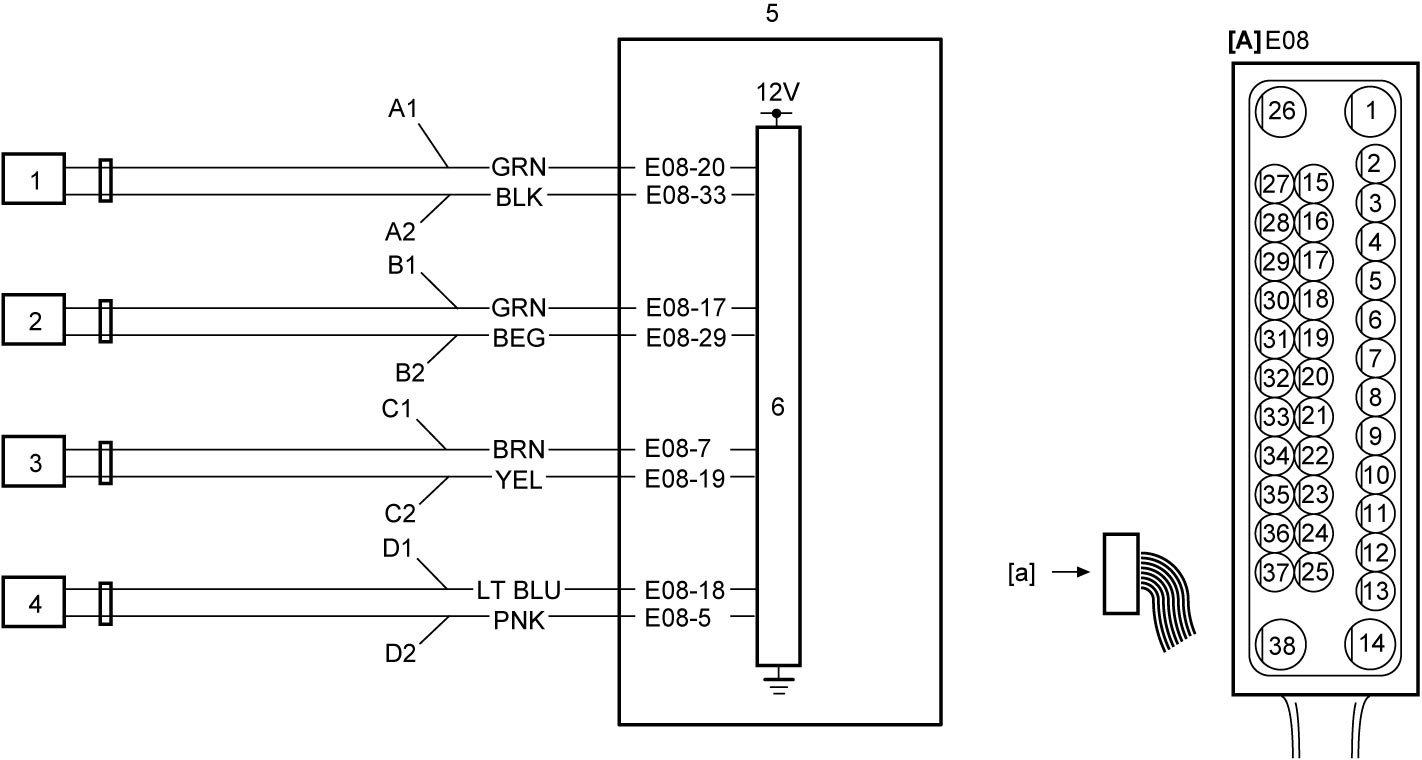
| [A]: | ESP® control module connector (View: [a]) | C1: | Left-rear wheel speed sensor power supply circuit | 2. | Right-front wheel speed sensor |
| A1: | Left-front wheel speed sensor power supply circuit | C2: | Left-rear wheel speed sensor signal circuit | 3. | Left-rear wheel speed sensor |
| A2: | Left-front wheel speed sensor signal circuit | D1: | Right-rear wheel speed sensor power supply circuit | 4. | Right-rear wheel speed sensor |
| B1: | Right-front wheel speed sensor power supply circuit | D2: | Right-rear wheel speed sensor signal circuit | 5. | ESP® control module |
| B2: | Right-front wheel speed sensor signal circuit | 1. | Left-front wheel speed sensor | 6. | Wheel speed sensor driver |
DTC Troubleshooting
Preparation
•Check that DTC C1057 is not detected.
•Perform the following procedure more than 8 times continuously.
•Perform the following procedure more than 8 times continuously.
1)Set ignition “ON”.
2)Drive vehicle at a speed of over 20 km/h (12 mile/h) for more than 1 minute.
3)Check that ignition is “OFF”.
| Step | Action | Yes | No |
|---|---|---|---|
| 1 |
Was “ESP® System Check” performed?
|
Go to Step 2.
|
Go to ESP® System Check.
|
| 2 |
Tire pressure check
1)Check that tire pressure is at specified value.
Is check result OK?
|
Go to Step 3.
|
Adjust tire pressure or replace tire and recheck DTC.
|
| 3 |
Wheel speed sensor power supply circuit and signal circuit check
1)Set ignition “OFF”.
2)Disconnect “E08” and wheel speed sensor connectors.
3)Check for proper connection to “E08” and each of wheel speed sensor connectors.
4)If connections are OK, check the following points.
•Resistance of “A1”, “A2”, “B1”, “B2”, “C1”, “C2”, “D1” and “D2” circuits: less than 1 Ω
•Resistance between each of “A1”, “A2”, “B1”, “B2”, “C1”, “C2”, “D1” and “D2” circuits and ground: infinity •Resistance between terminal “E08-20” and each of other terminals in “E08” connector, and resistance between terminal “E08-33” and each of other terminals in “E08” connector: infinity •Resistance between terminal “E08-17” and each of other terminals in “E08” connector, and resistance between terminal “E08-29” and each of other terminals in “E08” connector: infinity •Resistance between terminal “E08-7” and each of other terminals in “E08” connector, and resistance between terminal “E08-19” and each of other terminals in “E08” connector: infinity •Resistance between terminal “E08-18” and each of other terminals in “E08” connector, and resistance between terminal “E08-5” and each of other terminals in “E08” connector: infinity •Voltage of “A1”, “A2”, “B1”, “B2”, “C1”, “C2”, “D1” and “D2” circuits: approx. 0 V (When ignition is “ON”) Is check result OK?
|
Go to Step 4.
|
Repair or replace defective wire harness.
|
| 4 |
Wheel speed sensor signal check
1)Check applicable wheel speed sensor for output voltage and waveform.
Is check result as specified?
|
Replace ESP® hydraulic unit / control module assembly and recheck DTC.
|
Go to Step 5.
|
| 5 |
Wheel speed sensor check
1)Check applicable wheel speed sensor.
Is check result OK?
|
Go to Step 6.
|
Clean, repair or replace wheel speed sensor.
•Front wheel speed sensor:
•Rear wheel speed sensor: |
| 6 |
Wheel speed sensor encoder check
1)Check applicable wheel speed sensor encoder.
Is check result OK?
|
Replace ESP® hydraulic unit / control module assembly and recheck DTC.
|
Clean, repair or replace wheel speed sensor encoder.
•Front wheel speed sensor encoder:
•Rear wheel speed sensor encoder: |