DTC C1041 / C1042 / C1043 / C1044 / C1045 / C1046 / C1051 / C1052 / C1053 / C1054 / C1055 / C1056 / C1063
Precautions: Precautions for ESP® · Precautions for Diagnosing Trouble · Test with Speedometer Tester or Other Equipment · Precautions for Brakes · General safety (00)
DTC Detecting Condition and Trouble Area
| DTC detecting condition | Trouble area |
|---|---|
|
C1041 / C1045 / C1051 / C1055: Right-Front / Left-Front / Right-Rear / Left-Rear Inlet Solenoid Valve Circuit Correlation C1042 / C1046 / C1052 / C1056: Right-Front / Left-Front / Right-Rear / Left-Rear Outlet Solenoid Valve Circuit Correlation C1043 / C1044: Cut Solenoid No.1 / No.2 Valve Circuit Correlation C1053 / C1054: Low Pressure Solenoid No.1 / No.2 Valve Circuit Correlation Solenoid output and solenoid monitor data disagree. |
•ESP® control module power supply circuit
•ESP® control module ground circuit •ESP® control module |
|
C1063: Solenoid Valve Power Supply Driver Circuit Performance
•Solenoid valve power supply relay output is “ON”, although monitored output is “OFF”.
•Solenoid valve power supply relay output is “OFF”, although monitored output is “ON”. |
Circuit Diagram
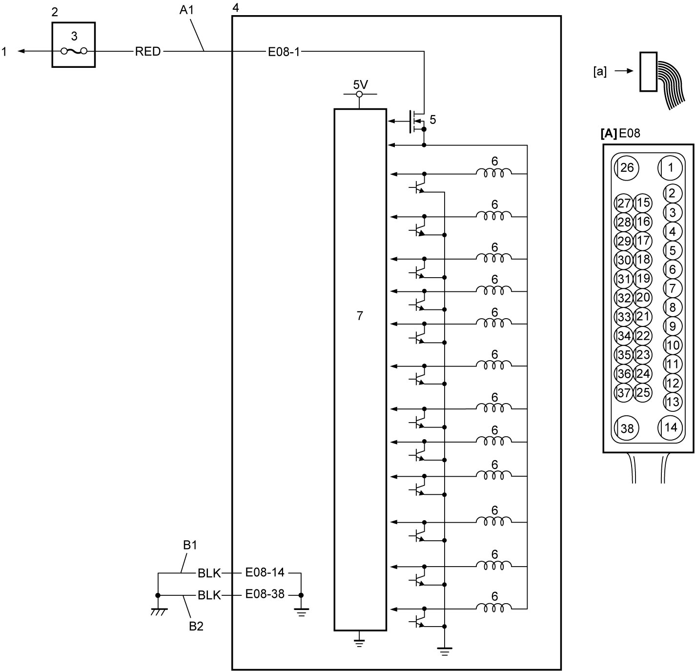
| [A]: | ESP® control module connector (View: [a]) | 1. | Lead to battery | 5. | Solenoid valve power supply relay |
| A1: | Solenoid valve power supply circuit | 2. | Relay box | 6. | Solenoid valve |
| B1: | ESP control module ground circuit 1 | 3. | “ABS2” fuse | 7. | CPU |
| B2: | ESP control module ground circuit 2 | 4. | ESP® control module |
DTC Troubleshooting
| Step | Action | Yes | No |
|---|---|---|---|
| 1 |
Was “ESP® System Check” performed?
|
Go to Step 2.
|
Go to ESP® System Check.
|
| 2 |
Solenoid valve power supply and ESP® control module ground circuit check
1)Check solenoid valve power supply and ground circuits under ESP® Control Module Power Supply and Ground Circuit Check.
Is check result OK?
|
Replace ESP® hydraulic unit / control module assembly and recheck DTC.

|
Repair or replace defective wire harness.
|