Valve Body Assembly Removal and Installation
Precautions: Precautions for Diagnosing Trouble · Precautions for Disassembly and Reassembly · Precautions for Transmission / Transaxle · General safety (00)
NOTICE:
•The transaxle side oil pan may become deformed during removal. If the removed transaxle side oil pan is reused, it may cause oil leakage. Do not reuse the side oil pan. Always install a new one.
•The transaxle side oil pan bolts are pre-coated with adhesive. If the bolts are reused, it may work loose.
Replace the transaxle side oil pan bolts with new ones.
•The transaxle side oil pan bolts are pre-coated with adhesive. If the bolts are reused, it may work loose.
Replace the transaxle side oil pan bolts with new ones.
NOTE:
When valve body assembly is removed or replaced, perform TCM Learning Value Clearance, Neutral Position Calibration and TCM Learning Value Initialization.
Removal
1)Disconnect negative (–) cable at battery.
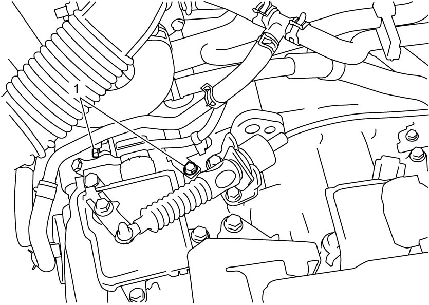
2)For M16A model, remove ATF cooler pipe bolts (1).

3)For K14C model, disconnect intercooler outlet hose No.1.
4)Hoist vehicle.
5)Remove engine undercover.
6)Drain A/T fluid. 
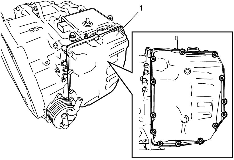
7)Remove transaxle side oil pan (1).
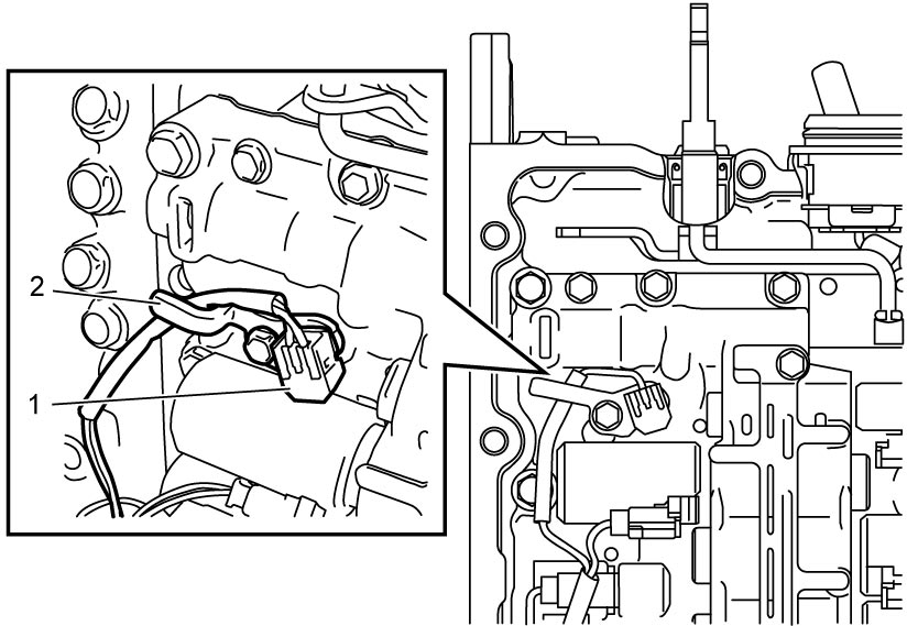
8)Remove ATF temperature sensor clamp bolt, and then remove ATF temperature sensor (1) and ATF temperature sensor clamp (2).
9)Disconnect solenoid connectors (1) and electro magnetic oil pump solenoid valve connector (2) (ENG A-STOP model) from solenoid valves.
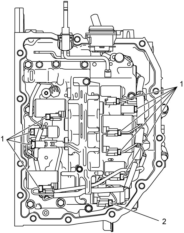
10)Disconnect output shaft speed sensor connector (1) from harness clamp.
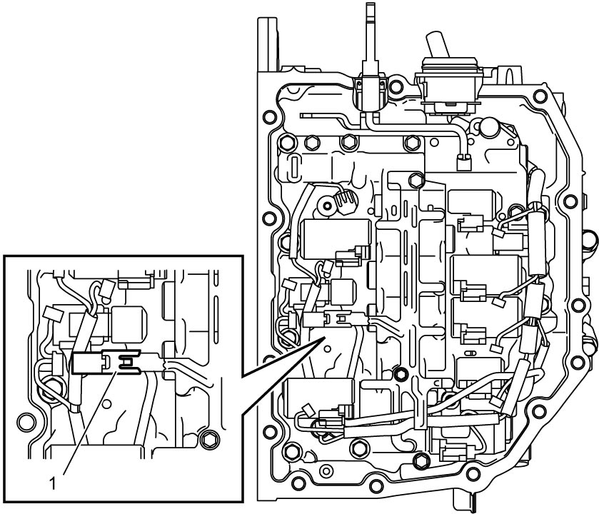
11)Remove valve body bolts, and then remove valve body assembly from transaxle case, being careful not to drop manual valve.
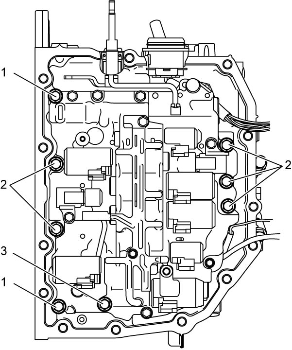
NOTE:
There are three types of bolts (bolts A (1), B (2) and C (3)) for fixing valve body assembly.
Installation
1)Install manual valve rod (1) to manual valve lever (2) and then install valve body assembly (3) to transaxle case.
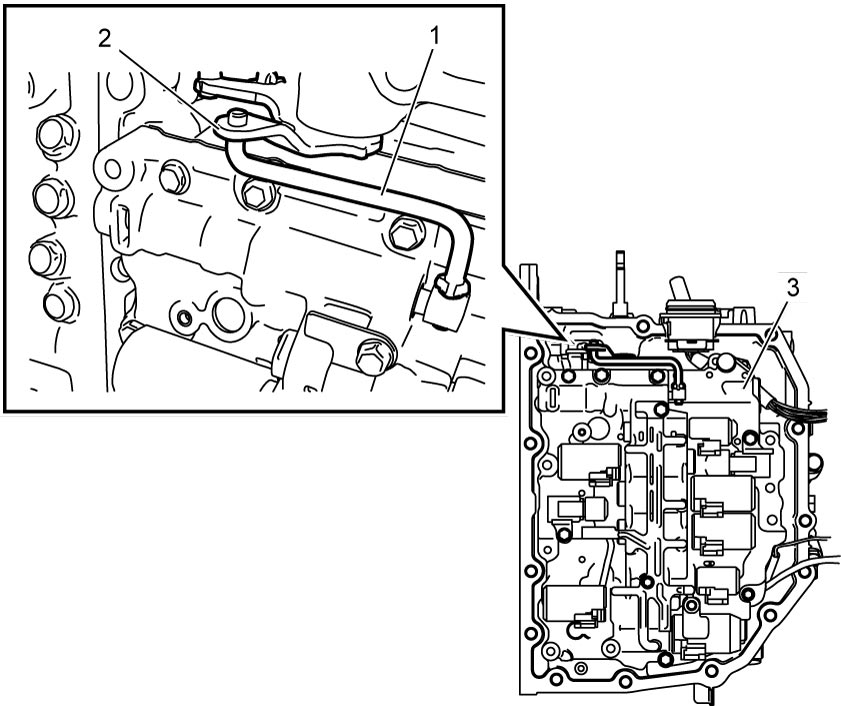
2)Tighten valve body bolts in numerical order (“1” – “8”) evenly and gradually to specified torque.
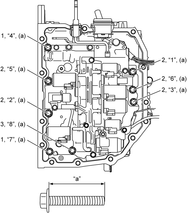
Valve body bolt length
| Bolt | Length “a” | Pieces |
|---|---|---|
| A (1) | 31 mm (1.22 in.) | 2 |
| B (2) | 21 mm (0.83 in.) | 5 |
| C (3) | 51 mm (2.01 in.) | 1 |
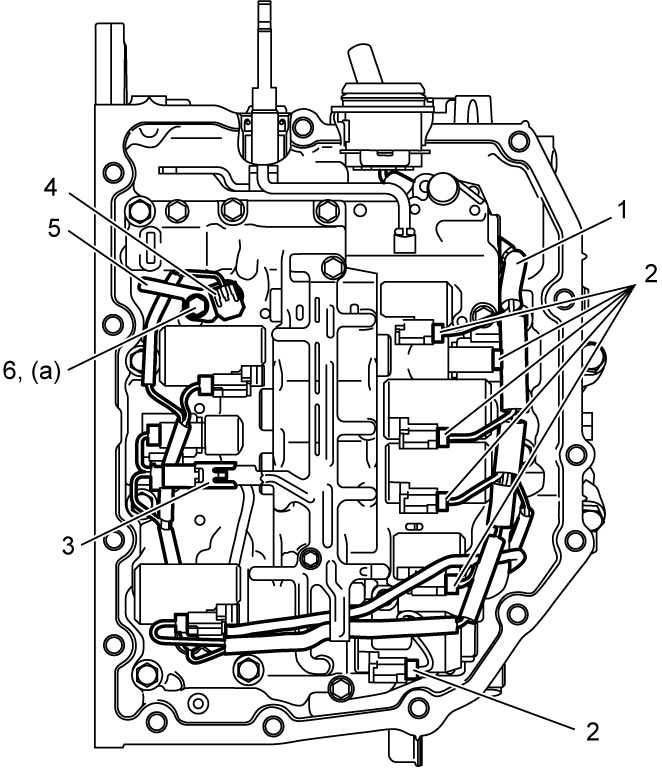
3)Install solenoid harness (1), and then connect solenoid connectors (2) and output shaft speed sensor connector (3) as shown in figure.
4)Install ATF temperature sensor (4) and ATF temperature sensor clamp (5), and then tighten ATF temperature sensor clamp bolt (6) to specified torque.
5)Apply sealant to mating surface of new transaxle side oil pan (1) as shown in figure.
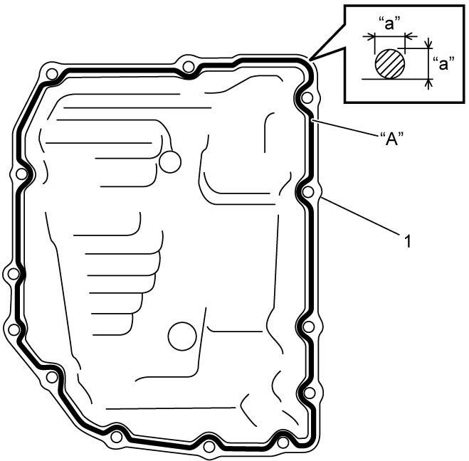
| “a”: | 2.5 mm (0.098 in.) |
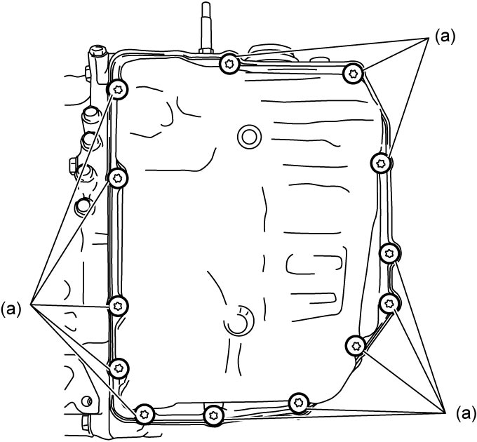
6)Tighten new transaxle side oil pan bolts to specified torque.
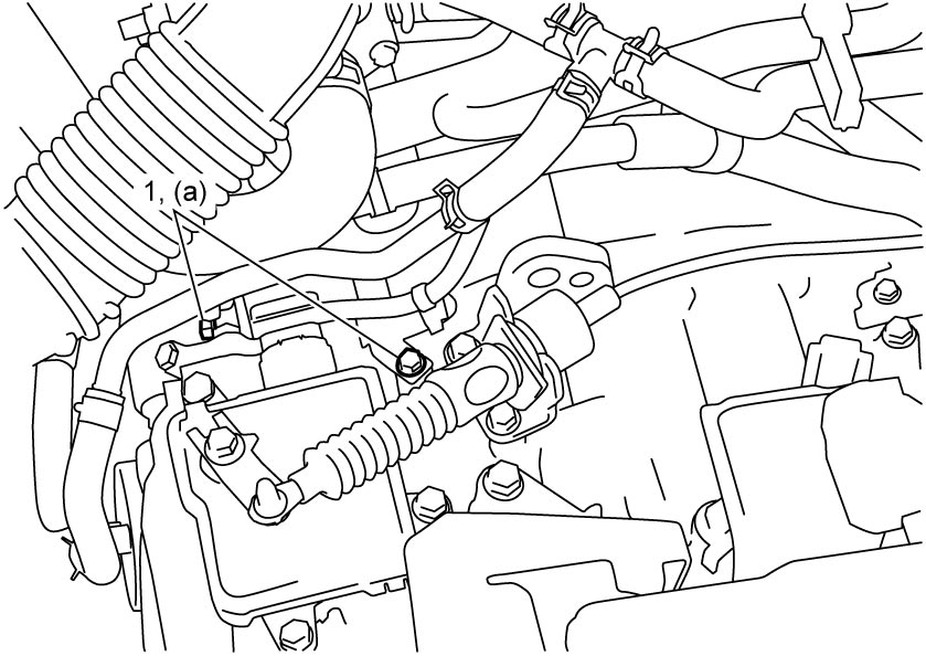
7)For M16A model, tighten ATF cooler pipe bolts (1) to specified torque.
8)For K14C model, connect intercooler hose No.1.
9)Install engine undercover.
10)Connect negative (–) cable at battery.
11)Refill A/T assembly with ATF.
12)Check ATF level.
13)Perform TCM Learning Value Clearance.
14)Perform Neutral Position Calibration.
15)Perform TCM Learning Value Initialization.