Input Shaft Disassembly and Reassembly
Precautions: General safety (00)
Disassembly
NOTICE:
Supporting the gear on the concave side of the puller can cause damage to the gear.
Support the gear on the flat side of the puller.
2)Remove input shaft right bearing (2) and left bearing (4) from input shaft (1) using bearing puller (3) and hydraulic press.
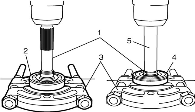

| 5. | Metal stick |
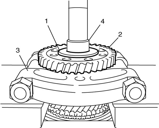
3)Remove 6th gear spacer (1) and 6th gear (2) from input shaft (4) using bearing puller (3) and hydraulic press.
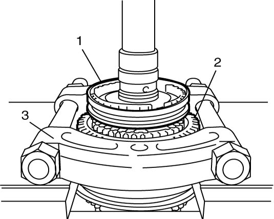
4)Remove 5th and 6th synchronizer sleeve & hub assembly (1) and 5th gear (2) using bearing puller (3) and hydraulic press.
5)Remove 5th gear needle bearing from input shaft.
6)Remove 5th gear spacer according to the following procedure.
a)Engage high speed synchronizer sleeve to 4th gear.
b)Push down input shaft (1) a little using bearing puller (2) and hydraulic press.
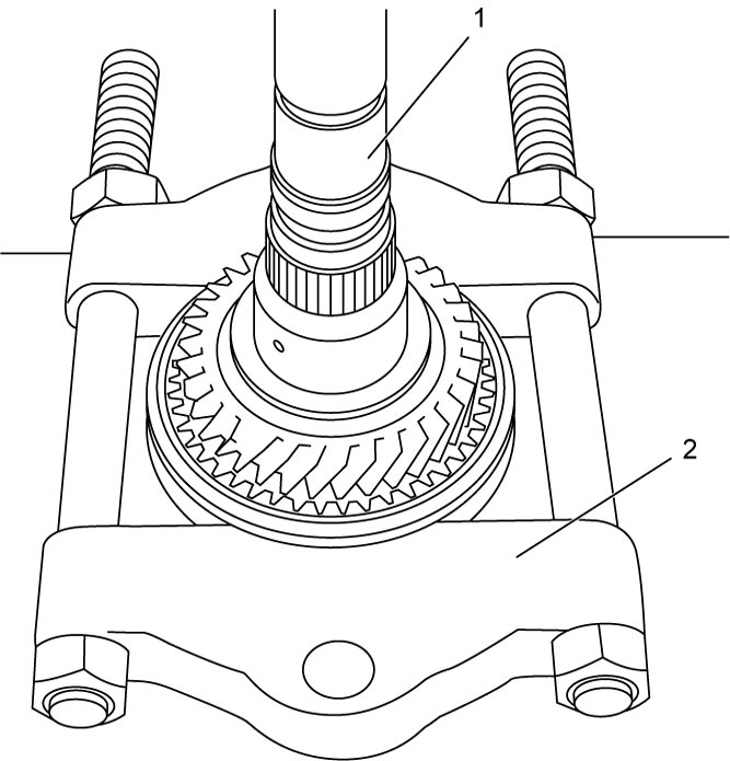
c)Remove 5th gear spacer (1) using bearing puller (2) and hydraulic press.
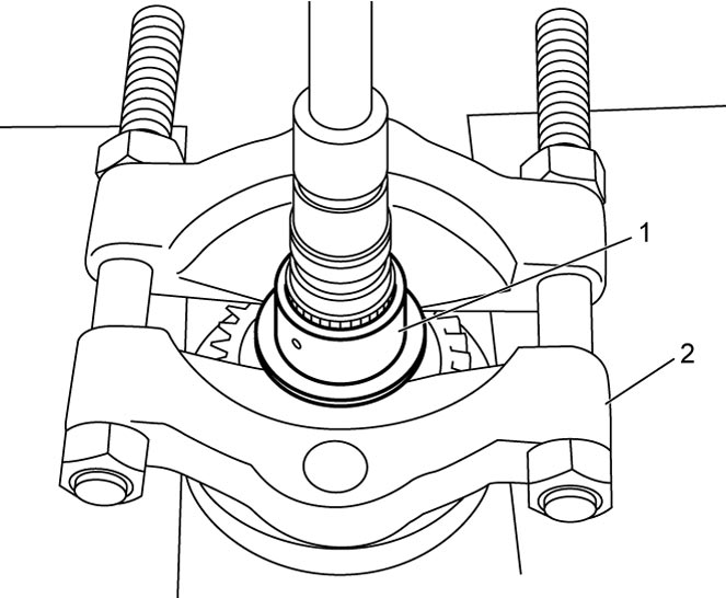
7)Remove 4th gear, 4th gear synchronizer ring and 4th gear needle bearing from input shaft.
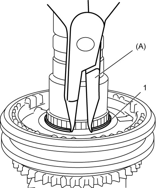
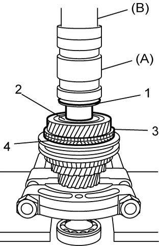
9)Remove high speed synchronizer sleeve & hub assembly (1) and 3rd gear (2) from input shaft (4) using bearing puller (3) and hydraulic press.
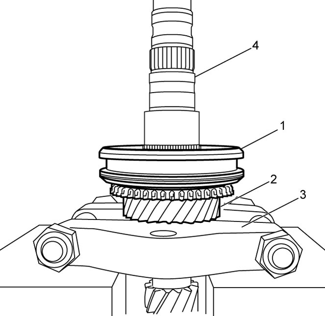
10)Remove 3rd gear needle bearing from input shaft.
11)Disassemble synchronizer sleeve & hub assembly.
Reassembly
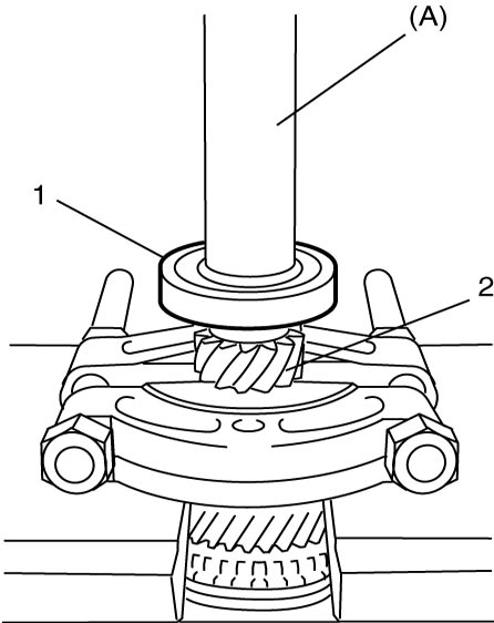
1)Install right bearing (1) to input shaft (2) using special tool and hydraulic press.
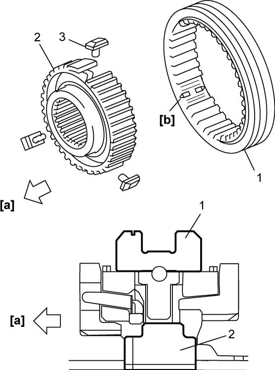
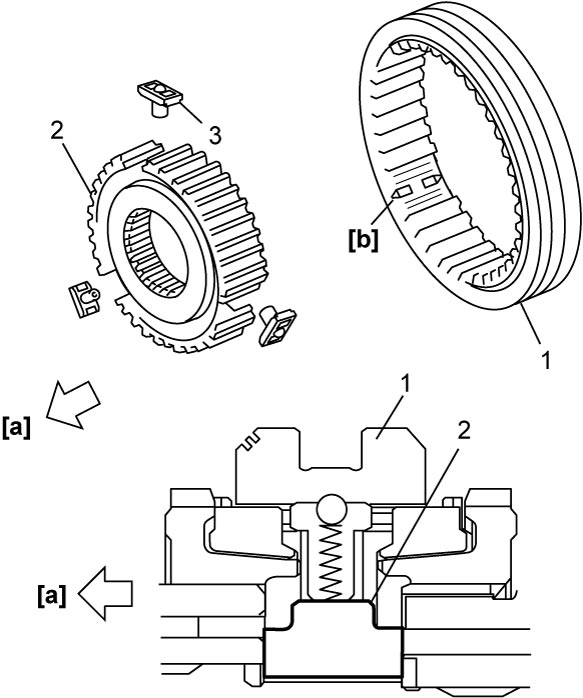
2)Fit high speed synchronizer sleeve (1) to hub (2) and 3 keys (3) as shown in figure.
NOTE:
•No specific direction is assigned to each key but it is assigned as sleeve & hub assembly.
•Inside diameter of high speed synchronizer hub is larger than that of low speed synchronizer hub.
•Inside diameter of high speed synchronizer hub is larger than that of low speed synchronizer hub.
Synchronizer key installation position
| [a]: | 3rd gear side | [b]: | Key way |
3)Install 3rd gear needle bearing and apply transaxle oil to it, and then install 3rd gear synchronizer inner ring (2), 3rd gear synchronizer center cone (3), 3rd gear synchronizer outer ring (4) and 3rd gear (1) to input shaft.
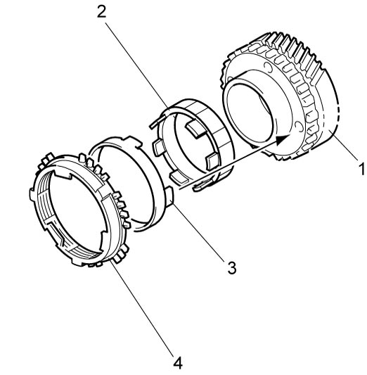
NOTE:
Make sure claws on 3rd gear synchronizer center cone fit into the holes on 3rd gear.
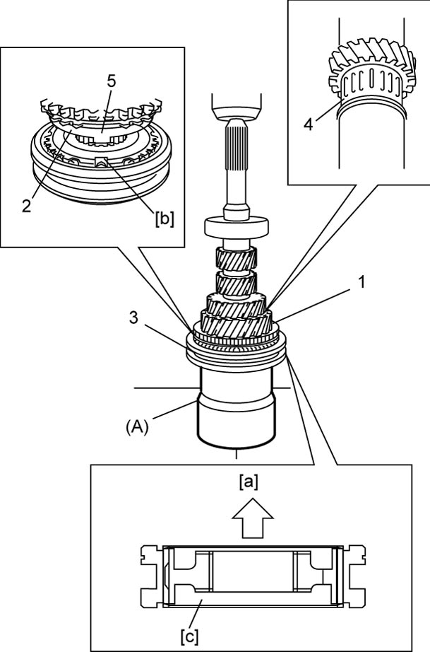
4)Install high speed sleeve & hub assembly (3) using special tool and hydraulic press and then install circlip.
NOTE:
•While press-fitting sleeve & hub, check that synchronizer ring key slots are aligned with keys (5) in sleeve & hub assembly.
•Check free rotation of 3rd gear (1) after press-fitting sleeve & hub assembly.
•Check free rotation of 3rd gear (1) after press-fitting sleeve & hub assembly.
| [a]: | 3rd gear side | 2. | Synchronizer ring |
| [b]: | Key slots | 4. | 3rd gear needle bearing |
| [c]: | Long flange |
5)Install 4th gear needle bearing (2) and apply transaxle oil to it, and then install synchronizer ring (4) and 4th gear (3).
6)Install 5th gear spacer (1) using special tools and hydraulic press.
 CAUTION:
CAUTION:
Using an inappropriate hydraulic press or bearing puller could cause personal injury.
Check that both the hydraulic press and bearing puller are capable of safely bearing a load of at least 5 tons (11,000 lbs).
7)Install 5th gear needle bearing and apply transaxle oil to it, and then install 5th gear and synchronizer ring.
8)Fit 5th & 6th gear synchronizer sleeve (1) to hub (2) and 3 keys (3) as shown in figure.
NOTE:
•No specific direction is assigned to 5th & 6th gear synchronizer hub or each key but it is assigned as assembly.
•Inside diameter at 5th & 6th gear synchronizer hub is smaller than that of low speed synchronizer hub.
•Inside diameter at 5th & 6th gear synchronizer hub is smaller than that of low speed synchronizer hub.
Synchronizer key installation position
| [a]: | 5th gear side | [b]: | Key way |
9)Install 5th & 6th gear synchronizer sleeve & hub assembly (1) using special tool and hydraulic press.
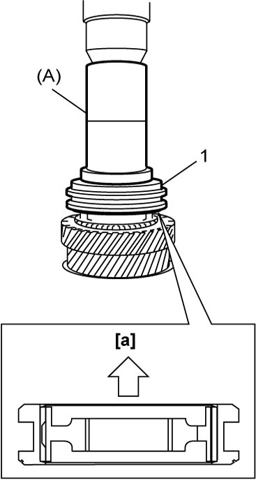
| [a]: | 6th gear side |
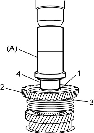
10)Install 6th gear needle bearing (1) and apply transaxle oil to it, and then install synchronizer ring (3) and 6th gear (2).
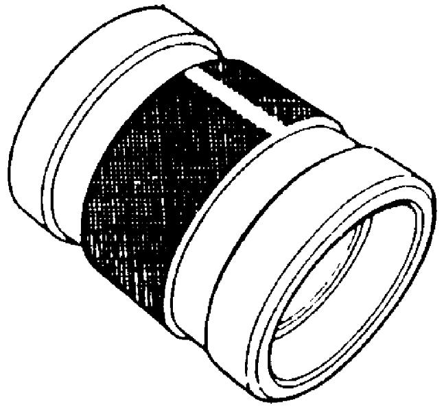
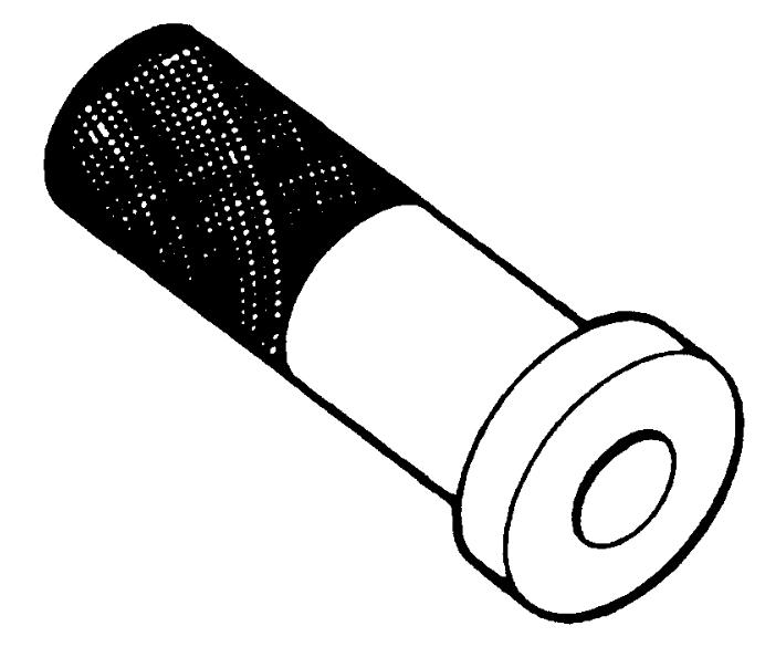
11)Install 6th gear spacer (4) using special tool and hydraulic press.
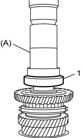
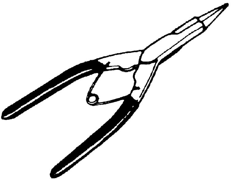
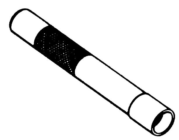
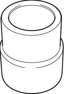
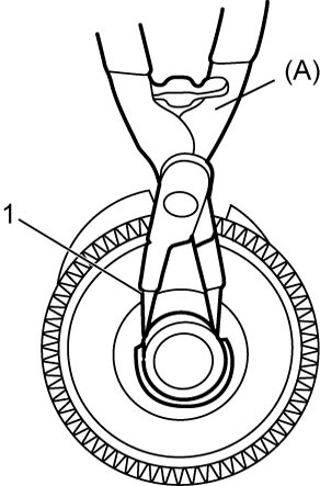
13)Select circlip (1) that makes thrust clearance “a” of bearing 0.1 mm (0.004 in) or less and install it.
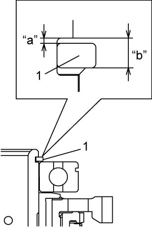
Available circlip thickness
| Clearance “b” | Circlip thickness |
|---|---|
| 1.810 – 1.860 mm (0.0713 – 0.0732 in.) |
1.81 mm (0.0713 in.) |
| 1.860 – 1.910 mm (0.0732 – 0.0751 in.) |
1.86 mm (0.0732 in.) |
| 1.910 – 1.960 mm (0.0751 – 0.0771 in.) |
1.91 mm (0.0751 in.) |
| 1.960 – 2.010 mm (0.0771 – 0.0791 in.) |
1.96 mm (0.0771 in.) |
| 2.010 – 2.060 mm (0.0791 – 0.0811 in.) |
2.01 mm (0.0791 in.) |
| 2.060 – 2.110 mm (0.0811 – 0.0831 in.) |
2.06 mm (0.0811 in.) |
| 2.110 – 2.160 mm (0.0831 – 0.0850 in.) |
2.11 mm (0.0831 in.) |
| 2.160 – 2.210 mm (0.0850 – 0.0870 in.) |
2.16 mm (0.0850 in.) |
| 2.210 – 2.260 mm (0.0870 – 0.0889 in.) |
2.21 mm (0.0870 in.) |
| 2.260 – 2.310 mm (0.0889 – 0.0909 in.) |
2.26 mm (0.0889 in.) |