Lower Countershaft Disassembly and Reassembly
Precautions: Precautions for Diagnosing Trouble · Precautions for Disassembly and Reassembly · Precautions for Transmission / Transaxle · General safety (00)
 CAUTION:
Using an inappropriate hydraulic press or bearing puller could cause personal injury.
Use the hydraulic press and bearing puller which are capable of safely bearing a load of at least 5 tons (11,000 lbs).
NOTICE:
Supporting the gear on the concave side of the puller can cause damage to the gear.
Support the gear on the flat side of the puller.
Disassembly
NOTE:
The lower countershaft bolt is of a left-handed thread type pre-coated with adhesive.
Therefore, turn clockwise when removing it.
However, adhered bolt with adhesive requires higher loosening torque than specified tightening torque.
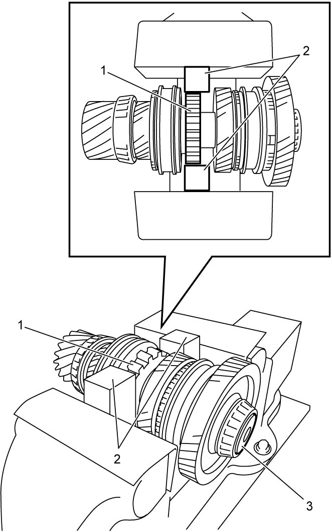
1)Hold parking lock wheel (1) with soft jawed vise and blocks (2) securely.
2)Remove lower countershaft bolt (3).

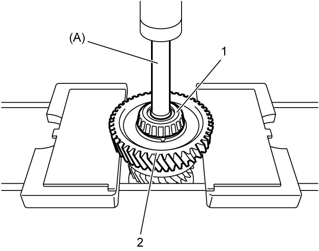
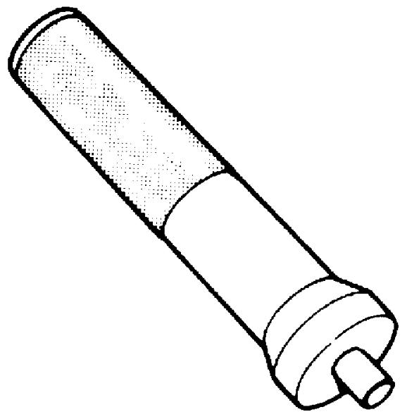
3)Remove lower countershaft left bearing (1) with 1st gear (2) using special tool and hydraulic press.
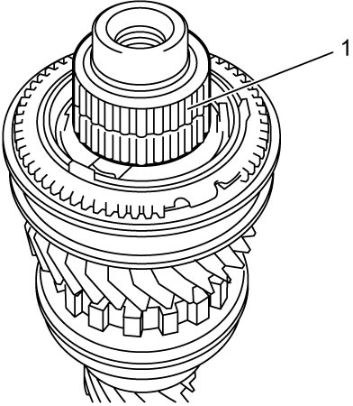
4)Remove 1st gear needle bearing (1).
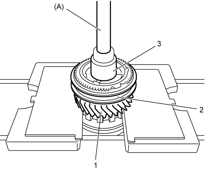
5)Remove 3rd gear (1) with 1st & 3rd gear synchronizer sleeve & hub (2) and 1st gear spacer (3) using special tool and hydraulic press.
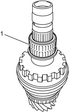
6)Remove 3rd gear needle bearing (1).
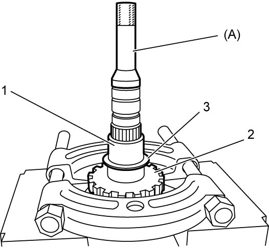
7)Remove parking lock wheel (2) with 3rd gear spacer (1) and washer (3) using special tool and hydraulic press.
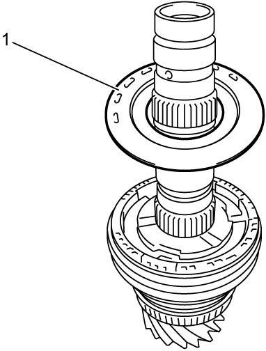
8)Remove parking lock wheel spacer (1).
9)Remove 6th gear (1) with 6th gear synchronizer sleeve & hub (2) using special tool and hydraulic press.
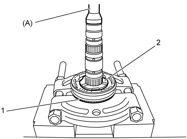
10)Remove 6th gear needle bearing (1).
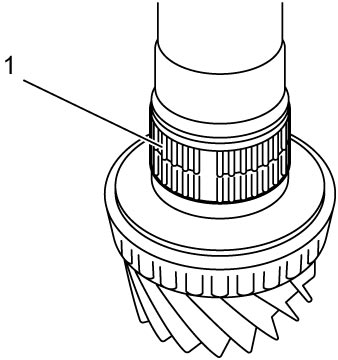
11)Remove circlip (1) using snap ring pliers (2), if necessary.
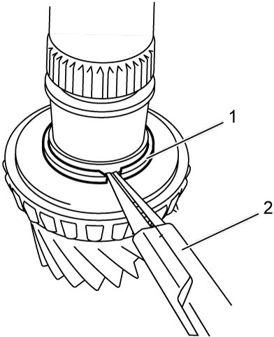
12)Remove lower countershaft right bearing (1) using hydraulic press.
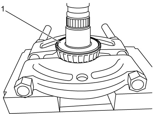
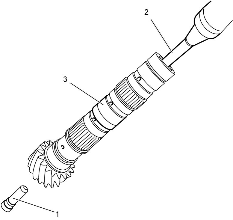
13)Remove lower countershaft plug (1) from lower countershaft (3) using flat-bladed screwdriver (2) or the like and hammer.
Reassembly
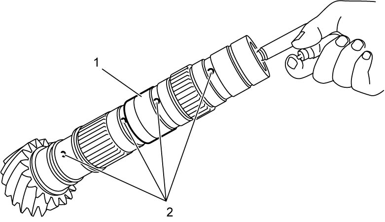
1)To ensure lubrication of lower countershaft (1), blow air into oil holes (2) and check that they are free from any obstruction.
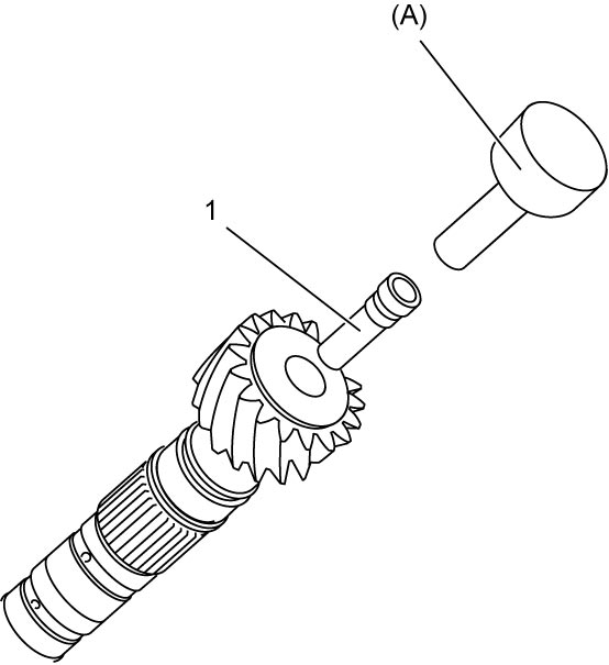
2)Install new lower countershaft plug (1) using special tool and hammer.
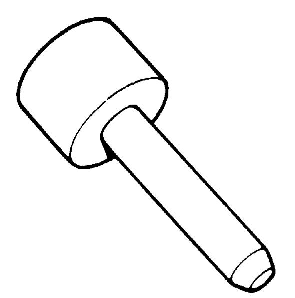
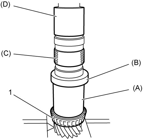
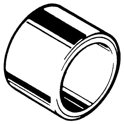
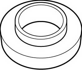
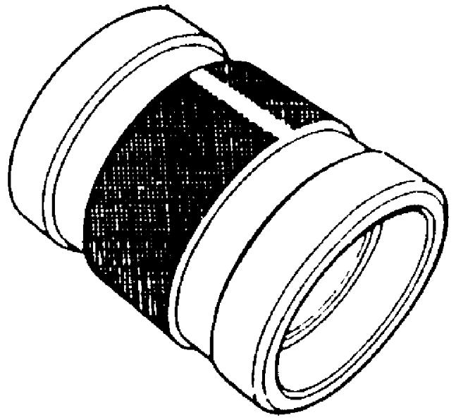
3)Install new lower countershaft right bearing (1) using special tools and hydraulic press.
4)Select new circlip as follows.
a)Measure clearance “a” between groove (1) of lower countershaft and lower countershaft right bearing (2) with feeler gauge (3).
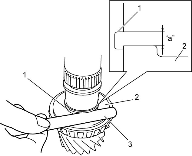
b)Select a circlip closest to the clearance “a” from the following available sizes.
Available circlip thickness
| Clearance “a” | Select circlip |
|---|---|
| 2.500 – 2.530 mm (0.0984 – 0.0996 in.) |
2.500 mm (0.0984 in.) |
| 2.530 – 2.560 mm (0.0996 – 0.1008 in.) |
2.530 mm (0.0996 in.) |
| 2.560 – 2.590 mm (0.1008 – 0.1020 in.) |
2.560 mm (0.1008 in.) |
| 2.590 – 2.620 mm (0.1020 – 0.1031 in.) |
2.590 mm (0.1020 in.) |
| Over 2.620 mm (0.1031 in.) | 2.620 mm (0.1031 in.) |
5)Install new circlip (1) using snap ring pliers (2).
6)Install 6th gear needle bearing (1) and apply oil to it.
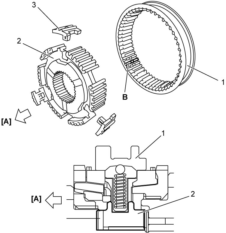
7)Fit 6th gear synchronizer sleeve (1) to hub (2), and insert 3 keys (3) as shown in figure.
NOTE:
No specific direction is assigned to 6th gear synchronizer sleeve or each key but it is assigned as assembly.
Synchronizer key installation position
| [A]: | 6th gear side | B: | Key way |
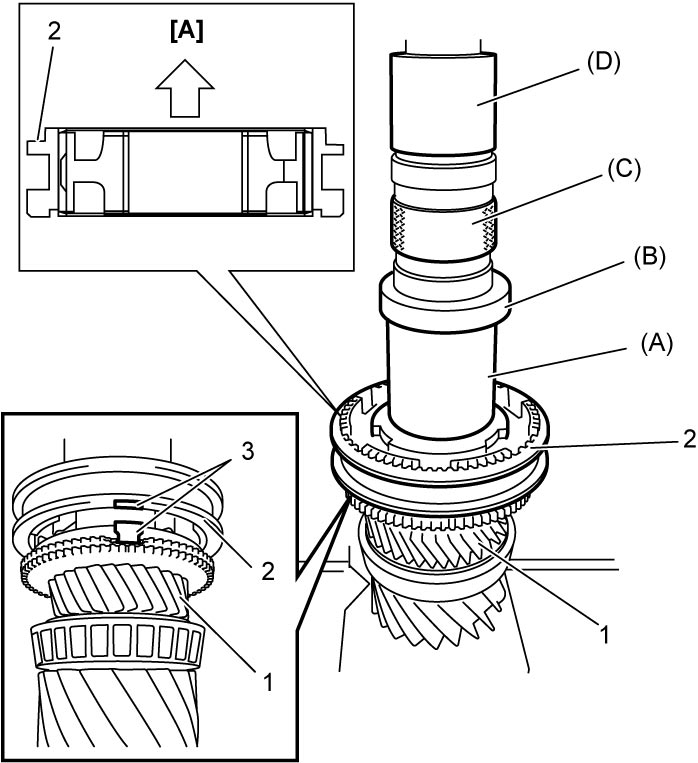
8)Install 6th gear (1) with 6th gear synchronizer sleeve & hub (2) using special tools and hydraulic press.
NOTE:
Check that synchronizer ring key slots are aligned with keys (3) while press-fitting sleeve & hub assembly.
| [A]: | 6th gear side |
9)Install parking lock wheel spacer and then parking lock wheel (1) using special tools and hydraulic press.
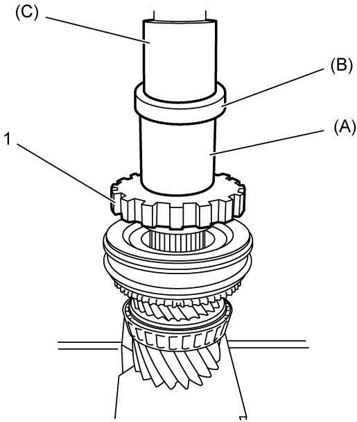
10)Install 3rd gear washer (1) and 3rd gear spacer (2) using special tool and hydraulic press.
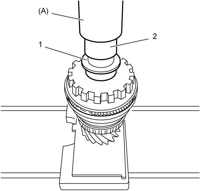
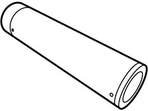
11)Install 3rd gear needle bearing (1) and apply oil to it.
12)Fit 1st & 3rd gear synchronizer sleeve (1) to hub (2), and insert 3 keys (3) as shown in figure.
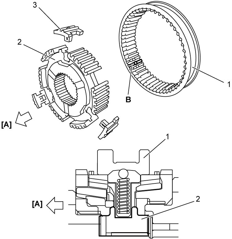
NOTE:
No specific direction is assigned to 1st & 3rd gear synchronizer sleeve or each key but it is assigned as assembly.
Synchronizer key installation position
| [A]: | 1st gear side | B: | Key way |
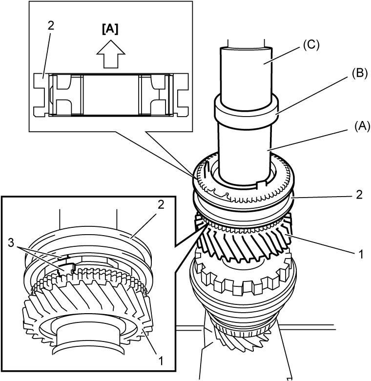
13)Install 3rd gear (1) with 1st & 3rd gear synchronizer sleeve & hub (2) using special tools and hydraulic press.
NOTE:
Check that synchronizer ring key slots are aligned with keys (3) while press-fitting sleeve & hub assembly.
| [A]: | 1st gear side |
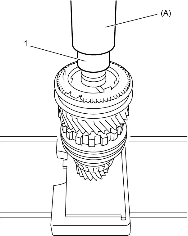
14)Install 1st gear spacer (1) using special tool and hydraulic press.
15)Install 1st gear needle bearing (1) and apply oil to it.
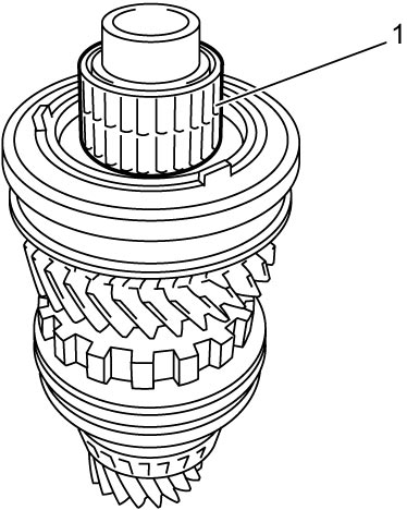
16)Install 1st gear (1) and lower countershaft left bearing (2) using special tool and hydraulic press.
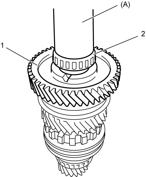
17)Hold parking lock wheel with soft jawed vise and blocks securely as shown.
18)Install new lower countershaft bolt (1) and tighten to specified torque.
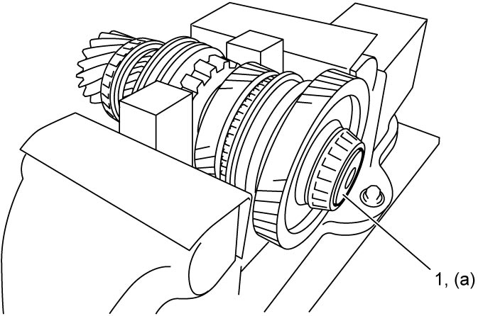
NOTICE:
The lower countershaft bolt is pre-coated with adhesive. If the bolt is reused, it may work loose.
Use the new lower countershaft bolt.
19)After replacing transaxle inner parts, perform TCM and Clutch Initialization.