DTC C1111 / C1113 / C1115 / C1116
Precautions: Precautions for Diagnosing Trouble · Precautions for Steering · General safety (00)
DTC Detecting Condition and Trouble Area
| DTC detecting condition | Trouble area |
|---|---|
|
C1111: Torque Sensor (Main) Circuit Malfunction Voltage of torque sensor signal (main) circuit is higher than specified value (4.5 V) or lower than specified value (0.5 V) for more than specified time. |
•Torque sensor (steering column assembly)
•Torque sensor circuit / connector •P/S control module (steering column assembly) |
|
C1113: Torque Sensor (Main and Sub) Signal Difference Voltage difference between torque sensor signal (main) circuit and torque sensor signal (sub) circuit remains too large for more than specified time. |
|
|
C1115: Torque Sensor (Sub) Circuit Malfunction Voltage of torque sensor signal (sub) circuit is higher than specified value (4.5 V) or lower than specified value (0.5 V) for more than specified time. |
|
|
C1116: Torque Sensor Power Supply (9 V) Circuit Malfunction Reference power supply voltage (9 V) for torque sensor circuit is lower than specified lower limit (7.0 V) for more than specified time. |
Circuit Diagram
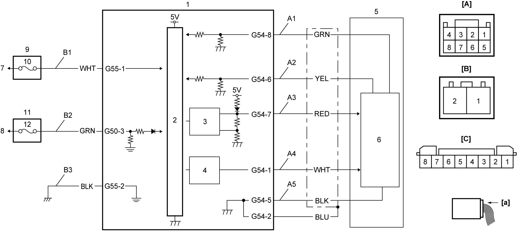
| [A]: | Torque sensor connector “G54” (View [a]) | B1. | P/S control module power supply circuit | 6. | Torque sensor amplifier |
| [B]: | P/S control module connector “G55” (View [a]) | B2. | IG1 power supply circuit | 7. | To continuous power supply |
| [C]: | P/S control module connector “G50” (View [a]) | B3. | P/S control module ground circuit | 8. | To ignition power supply |
| A1: | Torque sensor signal (main) circuit | 1. | P/S control module / motor assembly | 9. | Main fuse box |
| A2: | Torque sensor signal (sub) circuit | 2. | CPU | 10. | “P/S” fuse |
| A3: | 9 V power supply for torque sensor circuit | 3. | 9 V regulator | 11. | J/B |
| A4: | 3 V reference power supply for torque sensor circuit | 4. | 3 V reference power supply | 12. | “IG1 SIG” fuse |
| A5: | Torque sensor ground circuit | 5. | Torque sensor |
DTC Confirmation Procedure
Upon completion of initial check, turn steering wheel in both directions fully with vehicle stopped, and then handle steering while driving.
DTC Troubleshooting
| Step | Action | Yes | No |
|---|---|---|---|
| 1 |
Was “P/S System Check” performed?
|
Go to Step 2.
|
Go to P/S System Check and recheck DTC.
|
| 2 |
P/S control module power supply and ground circuit check
1)Check P/S control module power supply and ground circuits.

Is check result OK?
|
Go to Step 3.
|
Repair or replace defective wire harness.
|
| 3 |
P/S control module check
1)With ignition “OFF”, disconnect “G54” connector.
2)Check for proper connection to “G54” connector.
3)If connections are OK, set ignition “ON”.
4)Check that voltage between “G54” connector terminals.
•“G54-7” and “G54-5” is approx. 9 V.
•“G54-1” and “G54-5” is approx. 3.3 V. Is check result OK?
|
Go to Step 4.
|
Replace steering column assembly.
|
| 4 |
Torque sensor check
1)Check torque sensor.
Is the sensor in good condition?
|
Substitute a known-good steering column assembly and recheck DTC.
|
Replace steering column assembly.
|