DTC C1141 / C1142 / C1143 / C1145 / C1146
Precautions: Precautions for Diagnosing Trouble · Precautions for Steering · General safety (00)
DTC Detecting Condition and Trouble Area
| DTC detecting condition | Trouble area |
|---|---|
|
C1141: P/S Motor Circuit Voltage Malfunction Measured circuit voltage is higher than standard voltage by 0.3 V or more or motor drive circuit is defective. |
•P/S motor (steering column assembly)
•P/S control module (steering column assembly) |
|
C1142: P/S Motor Circuit Current Malfunction 1 Measured motor drive current is bigger than target value by 10 A or more. |
|
|
C1143: P/S Motor Circuit Current Too Big Measured motor drive current is more than 97 A. |
|
|
C1145: P/S Motor Circuit Current Malfunction 2 Target motor drive current is more than 4 A or measured value is less than 2 A. |
|
|
C1146: P/S Motor Voltage Malfunction Motor voltage calculated in P/S control module is abnormal. |
Circuit Diagram
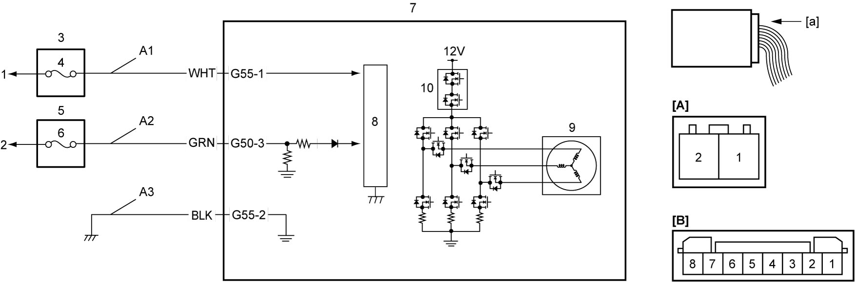
| [A]: | P/S control module connector “G55” (View: [a]) | 1. | To continuous power supply | 6. | “IG1 SIG” fuse |
| [B]: | P/S control module connector “G50” (View: [a]) | 2. | To ignition power supply | 7. | P/S control module / motor assembly |
| A1. | P/S control module power supply circuit | 3. | Main fuse box | 8. | CPU |
| A2. | IG1 power supply circuit | 4. | “P/S” fuse | 9. | P/S motor |
| A3. | P/S control module ground circuit | 5. | J/B | 10. | Fail-safe relay |
DTC Troubleshooting
| Step | Action | Yes | No |
|---|---|---|---|
| 1 |
Was “P/S System Check” performed?
|
Go to Step 2.
|
Go to P/S System Check and recheck DTC.
|
| 2 |
P/S control module power supply and ground circuit check
1)Check P/S control module power supply and ground circuits.

Is check result OK?
|
Substitute a known-good steering column assembly and recheck DTC.
|
Repair or replace defective wire harness.
|