HVAC System Description
Precautions: General safety (00)
•This HVAC system is of a manually controlled air conditioning type.
•Settings of air flow mode and temperature are possible using air flow selector and temperature selector respectively. When these selectors are set in desired positions, the corresponding cables move air flow control door and temperature control door accordingly.
•There are two other selectors: air intake switch and blower speed selector.
•Air inlet mode can be switched between recirculated air mode and fresh air mode by air intake switch. When the desired mode is selected, the air intake control actuator moves the air intake door to the corresponding position.
•Air flow rate can be adjusted by blower speed selector. Four positions are available: LO, ML, MH and HI.
•Rear defogger switch is located on the HVAC control unit.
•A/C switch turns on and off the A/C system. Signal from the A/C switch is transmitted to ECM via BCM through CAN communication system. The ECM circuits related to the A/C system control A/C compressor relay and radiator (condenser) cooling fan relay according to the signal. Refer to A/C Operation Description (Petrol Model):Manual Type or A/C Operation Description (Diesel Model):Manual Type for details.
•The ECM circuits related to the A/C system also control evaporator temperature depending on the data from evaporator temperature sensor. Refer to A/C Operation Description (Petrol Model):Manual Type or A/C Operation Description (Diesel Model):Manual Type for details. On the other hand, A/C compressor can adjust the flow rate of refrigerant, monitoring the A/C refrigerant pressure mechanically. This also helps to keep the evaporator temperature at an optimum level.
•The A/C system uses an A/C refrigerant pressure sensor that is capable of detecting linear changes in refrigerant pressure.
•HVAC unit incorporates blower motor unit, heater core unit and evaporator unit. The HVAC unit also incorporates an air filter.
•Each side ventilator has a shutter mechanism.
•The condenser is of a sub-cool type. It is integral with the receiver/dryer and mounted on the vehicle body in a floating manner.
•HVAC system on certain diesel model has additional heater system. The additional heater system works when the engine coolant is still cold after engine start.
•For further information on manual A/C system, refer to Manual A/C Control System Component Location:Manual Type, A/C System Major Components:Manual Type, Manual A/C Electronic Control Input / Output Block Diagram:Manual Type, Additional Heater (If Equipped) System Description:Manual Type and Additional Heater (If Equipped) Electronic Control Input / Output Block Diagram:Manual Type.
•Settings of air flow mode and temperature are possible using air flow selector and temperature selector respectively. When these selectors are set in desired positions, the corresponding cables move air flow control door and temperature control door accordingly.
•There are two other selectors: air intake switch and blower speed selector.
•Air inlet mode can be switched between recirculated air mode and fresh air mode by air intake switch. When the desired mode is selected, the air intake control actuator moves the air intake door to the corresponding position.
•Air flow rate can be adjusted by blower speed selector. Four positions are available: LO, ML, MH and HI.
•Rear defogger switch is located on the HVAC control unit.
•A/C switch turns on and off the A/C system. Signal from the A/C switch is transmitted to ECM via BCM through CAN communication system. The ECM circuits related to the A/C system control A/C compressor relay and radiator (condenser) cooling fan relay according to the signal. Refer to A/C Operation Description (Petrol Model):Manual Type or A/C Operation Description (Diesel Model):Manual Type for details.
•The ECM circuits related to the A/C system also control evaporator temperature depending on the data from evaporator temperature sensor. Refer to A/C Operation Description (Petrol Model):Manual Type or A/C Operation Description (Diesel Model):Manual Type for details. On the other hand, A/C compressor can adjust the flow rate of refrigerant, monitoring the A/C refrigerant pressure mechanically. This also helps to keep the evaporator temperature at an optimum level.
•The A/C system uses an A/C refrigerant pressure sensor that is capable of detecting linear changes in refrigerant pressure.
•HVAC unit incorporates blower motor unit, heater core unit and evaporator unit. The HVAC unit also incorporates an air filter.
•Each side ventilator has a shutter mechanism.
•The condenser is of a sub-cool type. It is integral with the receiver/dryer and mounted on the vehicle body in a floating manner.
•HVAC system on certain diesel model has additional heater system. The additional heater system works when the engine coolant is still cold after engine start.
•For further information on manual A/C system, refer to Manual A/C Control System Component Location:Manual Type, A/C System Major Components:Manual Type, Manual A/C Electronic Control Input / Output Block Diagram:Manual Type, Additional Heater (If Equipped) System Description:Manual Type and Additional Heater (If Equipped) Electronic Control Input / Output Block Diagram:Manual Type.
HVAC System Construction
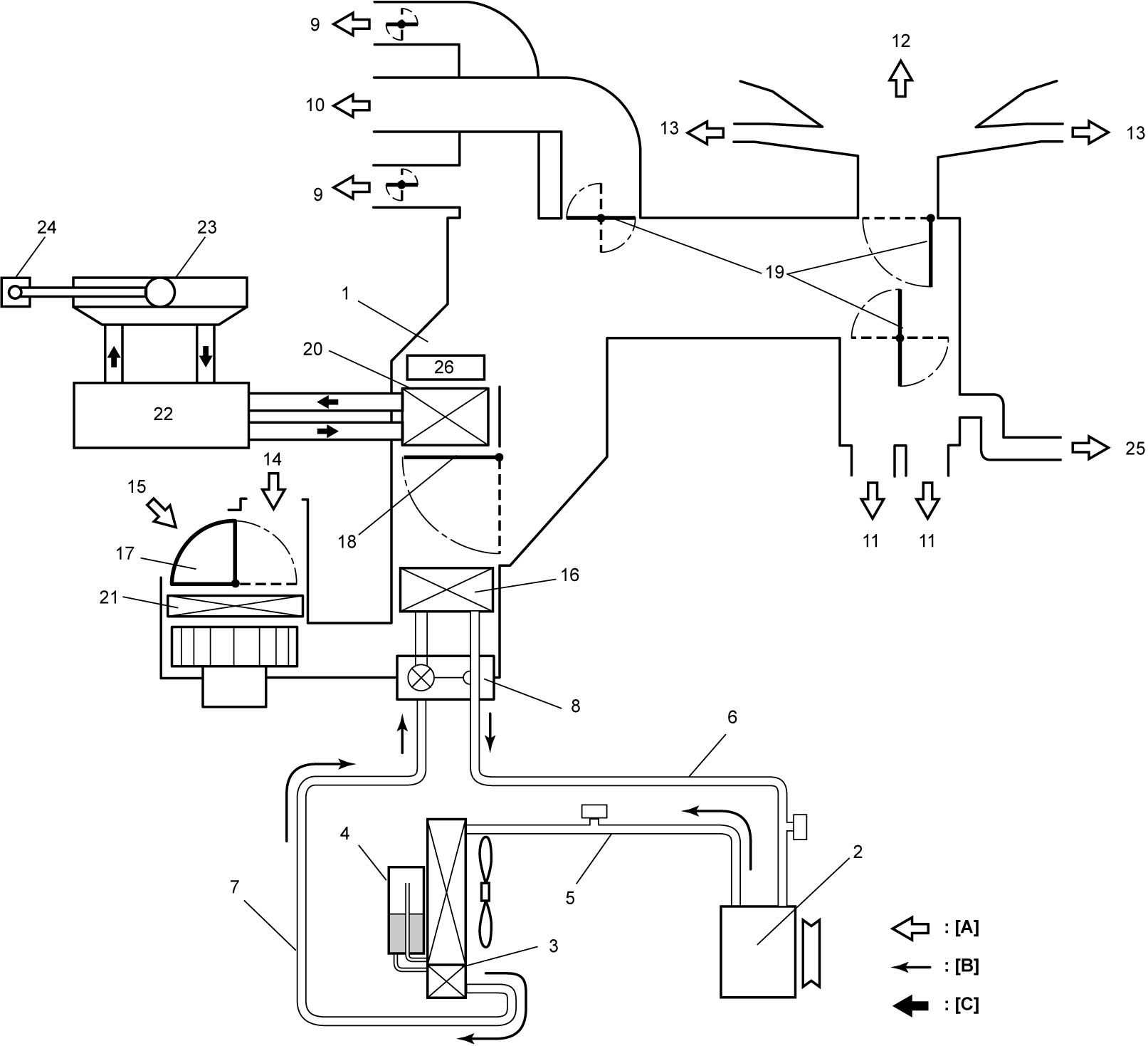
| [A]: | Air flow | 8. | Expansion valve | 18. | Temperature control door |
| [B]: | Refrigerant flow | 9. | Side ventilation air | 19. | Air flow control door |
| [C]: | Engine coolant flow | 10. | Center ventilation air | 20. | Heater core |
| 1. | HVAC unit | 11. | Front foot air | 21. | HVAC air filter |
| 2. | Compressor | 12. | Defroster air | 22. | Engine |
| 3. | Condenser assembly | 13. | Demister air | 23. | Radiator |
| 4. | Receiver/dryer | 14. | Fresh air | 24. | Reservoir |
| 5. | Discharge hose | 15. | Recirculation air | 25. | Rear foot air (if equipped) |
| 6. | Suction hose | 16. | Evaporator | 26. | Additional heater (if equipped) |
| 7. | Liquid pipe | 17. | Air intake door |