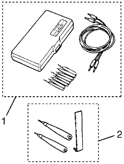
Contact Coil and Its Circuit Check
Precautions: Precautions for Air Bag System Service · Precautions for Handling and Storage of Air Bag System Components · Precautions for Disposal of Air Bag and Seat Belt Pretensioner · Precautions for Restraint · General safety (00)
Circuit Diagram
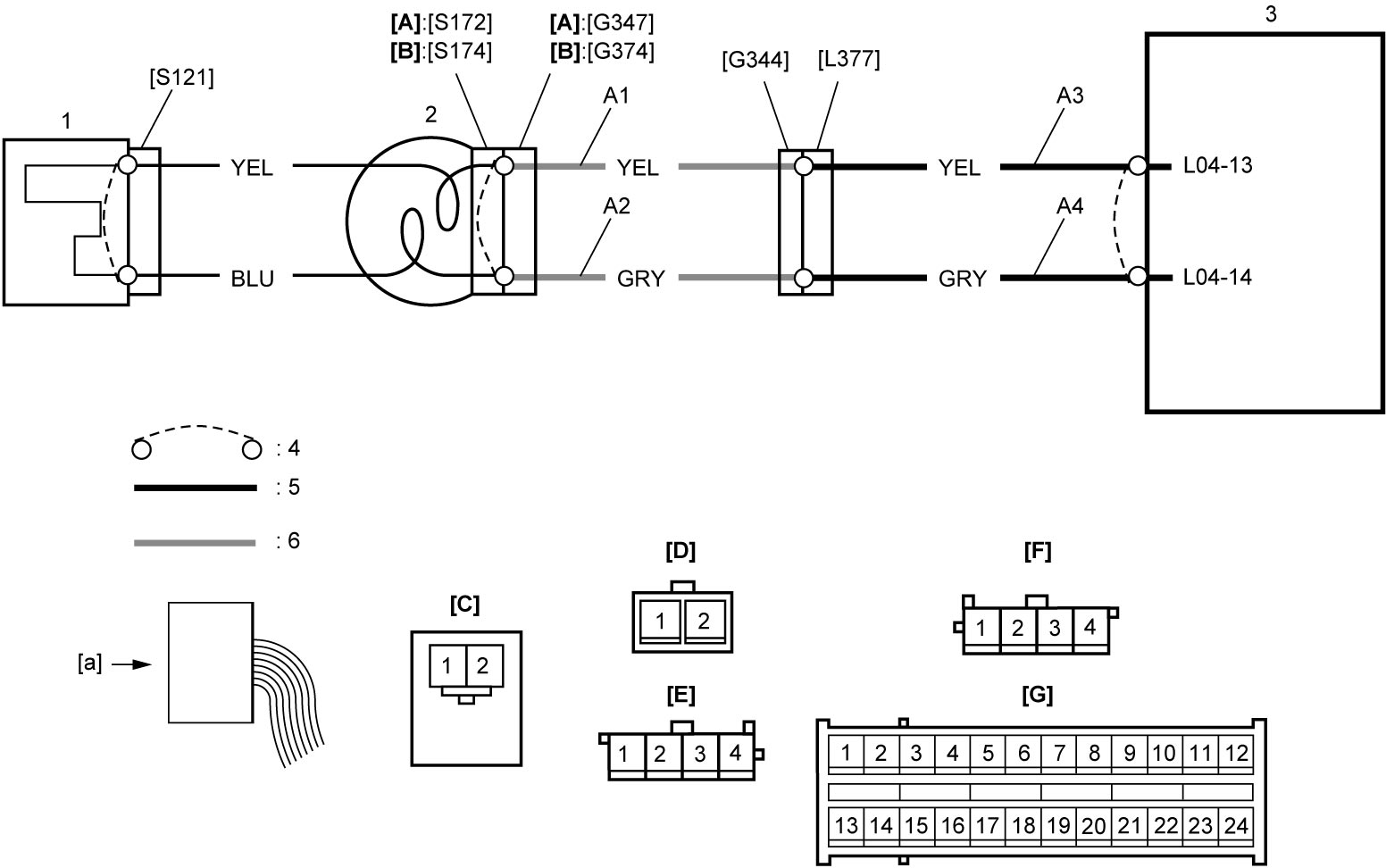
| [A]: | Without cruise control system | [G]: | “L04” connector (View: [a]) | 2. | Contact coil assembly |
| [B]: | With cruise control system | A1: | Driver air bag (inflator) module deployment signal output circuit | 3. | SDM |
| [C]: | “S121” connector (View: [a]) | A2: | Driver air bag (inflator) module deployment signal ground circuit | 4. | Shorting bar |
| [D]: | “G347” connector (View: [a]) | A3: | Driver air bag (inflator) module deployment signal output circuit | 5. | Floor harness |
| [E]: | “G374” connector (View: [a]) | A4: | Driver air bag (inflator) module deployment signal ground circuit | 6. | Instrument panel harness |
| [F]: | “G344” connector (View: [a]) | 1. | Driver air bag (inflator) module |
Troubleshooting
| Step | Action | Yes | No |
|---|---|---|---|
| 1 |
Driver air bag (inflator) module circuit check
1)Remove driver air bag (inflator) module from steering column.

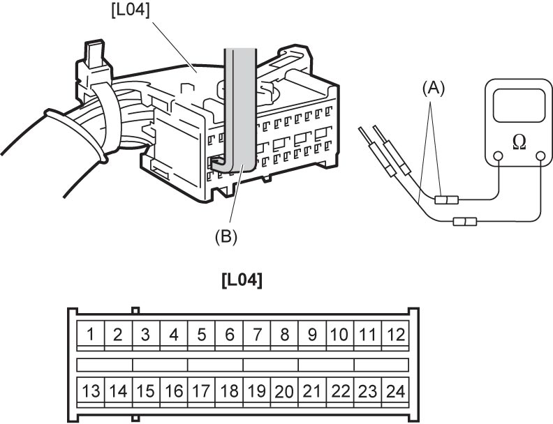
2)Disconnect “L04” connector.
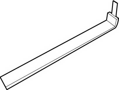
3)Release shorting bar in SDM connector inserting release tool (B).
4)Check the following point.
•Resistance between “L04-13” and “L04-14” terminals: infinity
 Is check result OK?
|
Go to Step 2.
|
Check for defective wire harness. If check result is OK, replace contact coil assembly.
|
| 2 |
Contact coil circuit (driver air bag (inflator) module circuit) check
1)Remove contact coil assembly.
2)Check the following points.
Without cruise control system:
•Measure resistance between “S121-1” to “S172-2” and “S121-2” to “S172-1” terminals. With cruise control system:
•Measure resistance between “S121-1” to “S174-1” and “S121-2” to “S174-2” terminals.
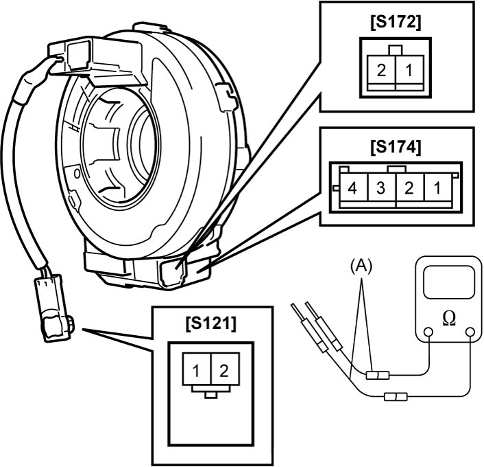 Is resistance 1 Ω or less?
|
Go to Step 3.
|
Replace contact coil assembly.
|
| 3 |
Contact coil circuit (horn circuit) check
1)Check the following point.
Without cruise control system:
•Measure resistance between “S61-1” and “S171-1” terminals. With cruise control system:
•Measure resistance between “S62-4” and “S173-4” terminals.
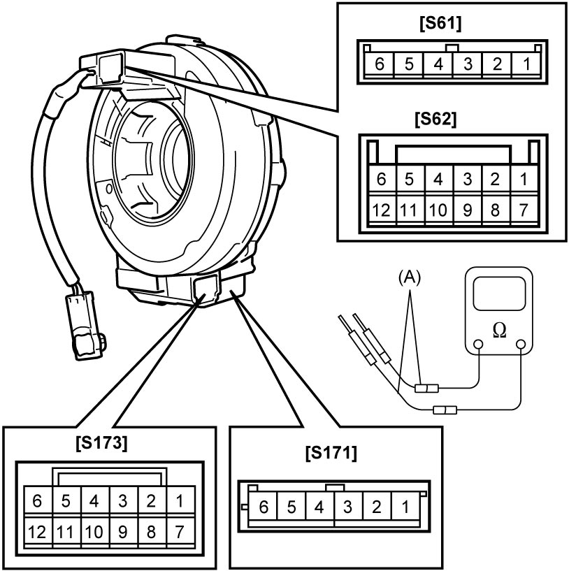 Is resistance 1 Ω or less?
|
Go to Step 4.
|
Replace contact coil assembly.
|
| 4 |
Contact coil circuit check
1)Measure resistance between each terminal of contact coil and other terminals.
Is each measured resistance infinite?
|
Contact coil and its circuit are in good condition.
|
Replace contact coil assembly.
|