Inspection of Keyless Entry Control Module and Its Circuits
Precautions: Precautions for Diagnosing Trouble · Precautions for Replacing Ignition Key (Ignition Switch Model) · Precautions for Transmitter Disposal (Ignition Switch Model) · Precautions for Replacing Keyless Entry Control Module (Ignition Switch Model) · Precautions for Body, Cab and Accessories · General safety (00)
Voltage and Signal Check
Check voltage and/or pulse signal of keyless entry control module (3) using voltmeter (1) and oscilloscope (2).
NOTE:
•Check that battery voltage is 12 V or more.
•Voltage of terminal with asterisk (*) cannot be measured by voltmeter because it is pulse signal. Check it with oscilloscope if necessary.
•Voltage of terminal with asterisk (*) cannot be measured by voltmeter because it is pulse signal. Check it with oscilloscope if necessary.
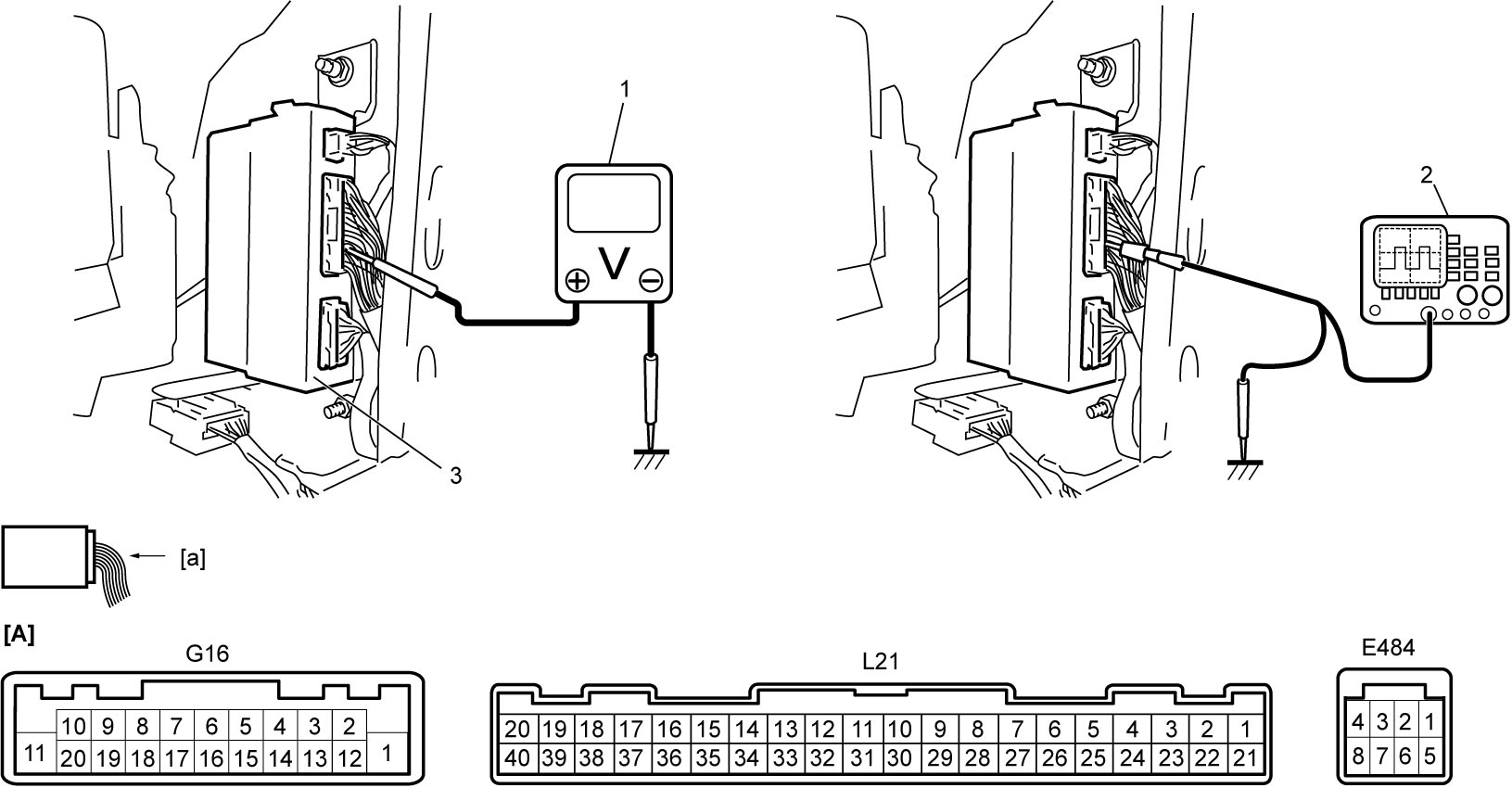
| [A]: | Keyless entry control module connector (View: [a]) |
“E484” connector
| Terminal No. | Wire color | Circuit | Normal voltage | Condition |
|---|---|---|---|---|
| E484-1 | BRN | Backup power supply | 10 – 14 V | — |
| E484-2* | BLU | Hood latch switch signal (if equipped) | Refer to Hood latch switch signal, door key cylinder switch signal, rear end door switch signal, door switch signal and rear end door opener switch signal. | |
| Approx. 0 V | Hood latch: Latch released | |||
| E484-3 | RED | Horn relay | Approx. 0 V | Horn: Sounding |
| 10 – 14 V | Other than above condition | |||
| E484-8 | PNK | Power supply for starting motor control relay (if equipped) | 10 – 14 V | Engine: Cranking |
| Approx. 0 V | Other than above condition | |||
“G16” connector
| Terminal No. | Wire color | Circuit | Normal voltage | Condition |
|---|---|---|---|---|
| G16-6 | YEL | Immobilizer control module | — | — |
| G16-7 | GRN | Immobilizer control module | — | — |
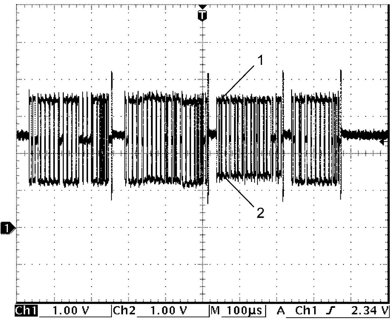
| G16-9* | RED | CAN communication line (high) | Refer to CAN communication signal. | |
| G16-13 | BLK | Immobilizer control module | — | — |
| G16-14 | GRY | Ground for keyless entry control module | Approx. 0 V | — |
| G16-16 | LT GRN | Theft deterrent light signal | 0 ← → 14 V | Theft deterrent light: Blinking |
| 10 – 14 V | Other than above condition | |||
| G16-17 | GRY | Immobilizer control module | — | — |
| G16-18 | BLU | Ignition switch illumination signal | Approx. 0 V | Ignition switch illumination: Lit |
| 10 – 14 V | Ignition switch illumination: Not lit | |||
| G16-19* | WHT | CAN communication line (low) | Refer to CAN communication signal. | |
“L21” connector
| Terminal No. | Wire color | Circuit | Normal voltage | Condition |
|---|---|---|---|---|
| L21-13* | BRN | Door key cylinder switch signal (Unlock) | Refer to Hood latch switch signal, door key cylinder switch signal, rear end door switch signal, door switch signal and rear end door opener switch signal. | |
| Approx. 0 V | Door key cylinder switch: Unlocked | |||
| L21-14* | GRN | Rear end door switch signal | Refer to Hood latch switch signal, door key cylinder switch signal, rear end door switch signal, door switch signal and rear end door opener switch signal. | |
| Approx. 0 V | Rear end door: Opened | |||
| L21-15* | BLU | Rear door switch signal (R) | Refer to Hood latch switch signal, door key cylinder switch signal, rear end door switch signal, door switch signal and rear end door opener switch signal. | |
| Approx. 0 V | Rear door (R): Opened | |||
| L21-16* | PNK | Driver door switch signal | Refer to Hood latch switch signal, door key cylinder switch signal, rear end door switch signal, door switch signal and rear end door opener switch signal. | |
| Approx. 0 V | Driver door: Opened | |||
| L21-18* | BLU | Door key cylinder switch signal (Lock) | Refer to Hood latch switch signal, door key cylinder switch signal, rear end door switch signal, door switch signal and rear end door opener switch signal. | |
| Approx. 0 V | Door key cylinder switch: Locked | |||
| L21-19 | LT BLU | Power source (ACC) | 10 – 14 V | Ignition: “ACC” or “ON” |
| Approx. 0 V | Other than above condition | |||
| L21-20 | RED | Backup power supply | 10 – 14 V | — |
| L21-34* | WHT | Rear door switch signal (L) | Refer to Hood latch switch signal, door key cylinder switch signal, rear end door switch signal, door switch signal and rear end door opener switch signal. | |
| Approx. 0 V | Rear door (L): Opened | |||
| L21-35* | RED | Passenger door switch signal | Refer to Hood latch switch signal, door key cylinder switch signal, rear end door switch signal, door switch signal and rear end door opener switch signal. | |
| Approx. 0 V | Passenger door: Opened | |||
| L21-36 | BLK | Ground for keyless entry control module | Approx. 0 V | — |
| L21-37* | LT GRN | Rear end door opener switch | Refer to Hood latch switch signal, door key cylinder switch signal, rear end door switch signal, door switch signal and rear end door opener switch signal. | |
| Approx. 0 V | Rear end opener switch: Pushed | |||
| L21-38 | PNK | Ignition “ST” signal (if equipped) | 10 – 14 V | Ignition: “ST” |
| Approx. 0 V | Other than above condition | |||
| L21-39 | GRN | Power source (IG) | 10 – 14 V | Ignition: “ON” |
| Approx. 0 V | Other than above condition | |||
| L21-40 | BLU | Key reminder switch signal | 10 – 14 V | Ignition key: Inserted to ignition key cylinder |
| Approx. 0 V | Ignition key: Pulled out from ignition key cylinder | |||
Reference Waveform
Oscilloscope display
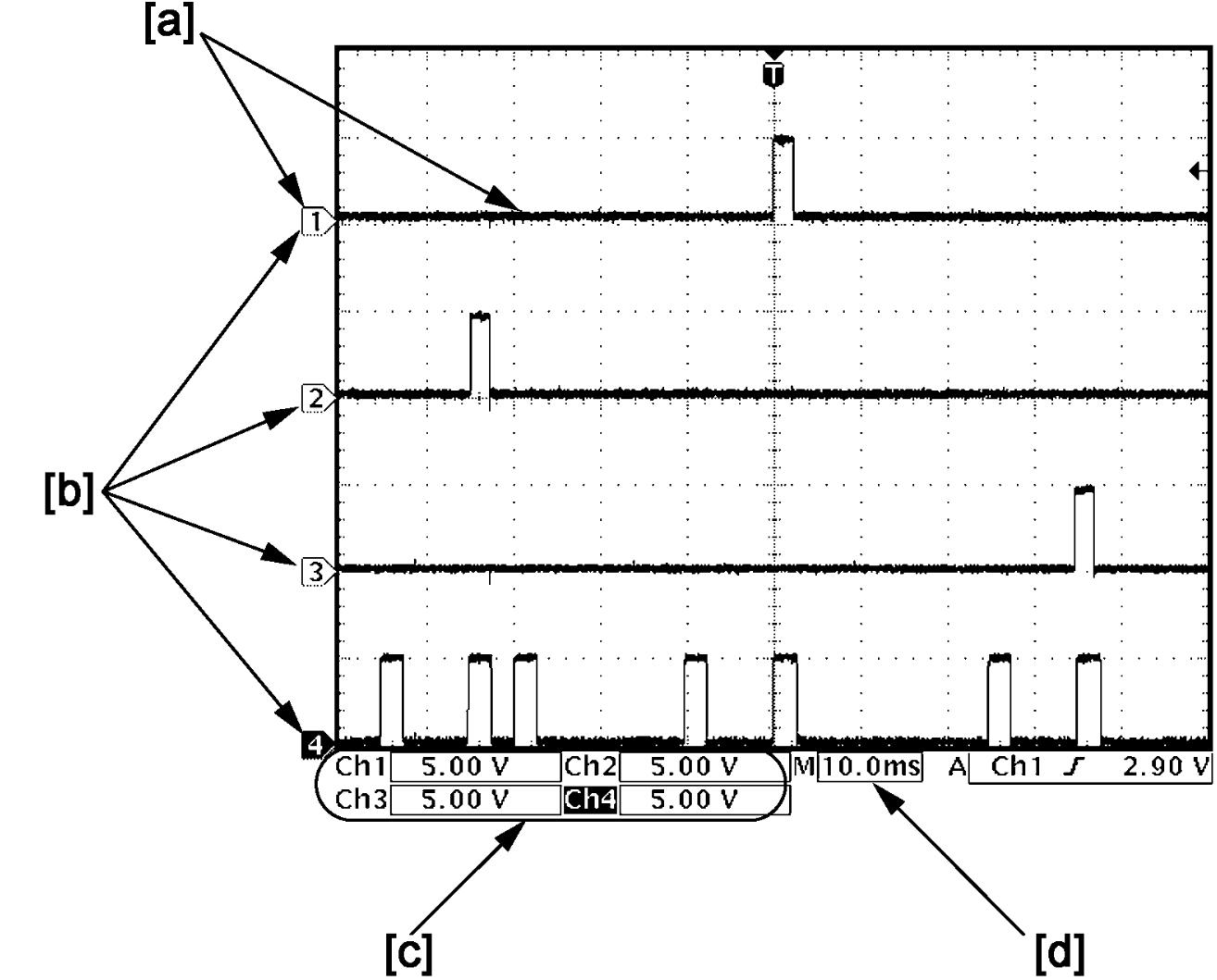
Shown below is typical waveform display provided by oscilloscope.
NOTE:
•How to read waveforms is shown below.

•Waveform varies depending on measurement condition and vehicle spec.
| [a]: | Waveform of channel 1 | [c]: | VOLT/DIV of each channel |
| [b]: | Ground level of each channel | [d]: | TIME/DIV |
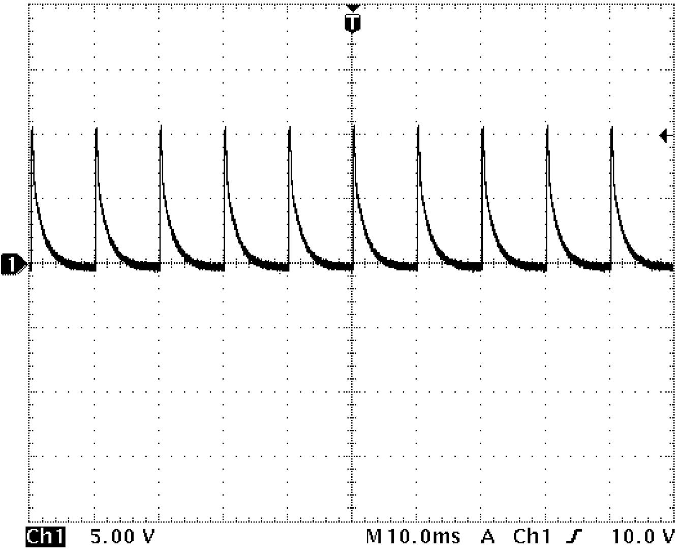
Hood latch switch signal, door key cylinder switch signal, rear end door switch signal, door switch signal and rear end door opener switch signal
Hood latch switch signal
| Channel | Probe | Terminal No. |
|---|---|---|
| 1 | + | E484-2 |
| – | G16-14 |
Measurement condition
•Hood latch: Fully latched
Door key cylinder switch (Unlock) signal
| Channel | Probe | Terminal No. |
|---|---|---|
| 1 | + | L21-13 |
| – | G16-14 |
Measurement condition
•Door key cylinder switch (Unlock): OFF
Rear end door switch signal
| Channel | Probe | Terminal No. |
|---|---|---|
| 1 | + | L21-14 |
| – | G16-14 |
Measurement condition
•Rear end door: Closed
Rear door switch signal (R)
| Channel | Probe | Terminal No. |
|---|---|---|
| 1 | + | L21-15 |
| – | G16-14 |
Measurement condition
•Rear door (R): Closed
Driver door switch signal
| Channel | Probe | Terminal No. |
|---|---|---|
| 1 | + | L21-16 |
| – | G16-14 |
Measurement condition
•Driver door: Closed
Door key cylinder switch (Lock) signal
| Channel | Probe | Terminal No. |
|---|---|---|
| 1 | + | L21-18 |
| – | G16-14 |
Measurement condition
•Door key cylinder switch (Lock): OFF
Rear door switch signal (L)
| Channel | Probe | Terminal No. |
|---|---|---|
| 1 | + | L21-34 |
| – | G16-14 |
Measurement condition
•Rear door (L): Closed
Passenger door switch signal
| Channel | Probe | Terminal No. |
|---|---|---|
| 1 | + | L21-35 |
| – | G16-14 |
Measurement condition
•Passenger door: Closed
Rear end door opener switch signal
| Channel | Probe | Terminal No. |
|---|---|---|
| 1 | + | L21-37 |
| – | G16-14 |
Measurement condition
•Rear end door opener switch: Released
CAN communication signal
CAN communication signal (High) (1)
| Channel | Probe | Terminal No. |
|---|---|---|
| 1 | + | G16-9 |
| – | G16-14 |
CAN communication signal (Low) (2)
| Channel | Probe | Terminal No. |
|---|---|---|
| 2 | + | G16-19 |
| – | G16-14 |
Measurement condition
•Ignition: “ON”