Front Underbody Dimensions with Mechanical Parts
Precautions: Precautions for Body Structure · Precautions for Body, Cab and Accessories · General safety (00)
NOTE:
•Values in this dimensional drawing are provided for reference only. Refer to Underbody Dimensions when correct values are needed.
•Dimension with asterisk (*) shows distance to the same point on opposite side.
•In principle, body dimensions in the figure below are symmetrical. Adopt the dimension for the opposite side if the dimension is not mentioned in the figure below.
•The number with “ø” is circle diameter and measurement unit is “mm”.
•Dimension with asterisk (*) shows distance to the same point on opposite side.
•In principle, body dimensions in the figure below are symmetrical. Adopt the dimension for the opposite side if the dimension is not mentioned in the figure below.
•The number with “ø” is circle diameter and measurement unit is “mm”.
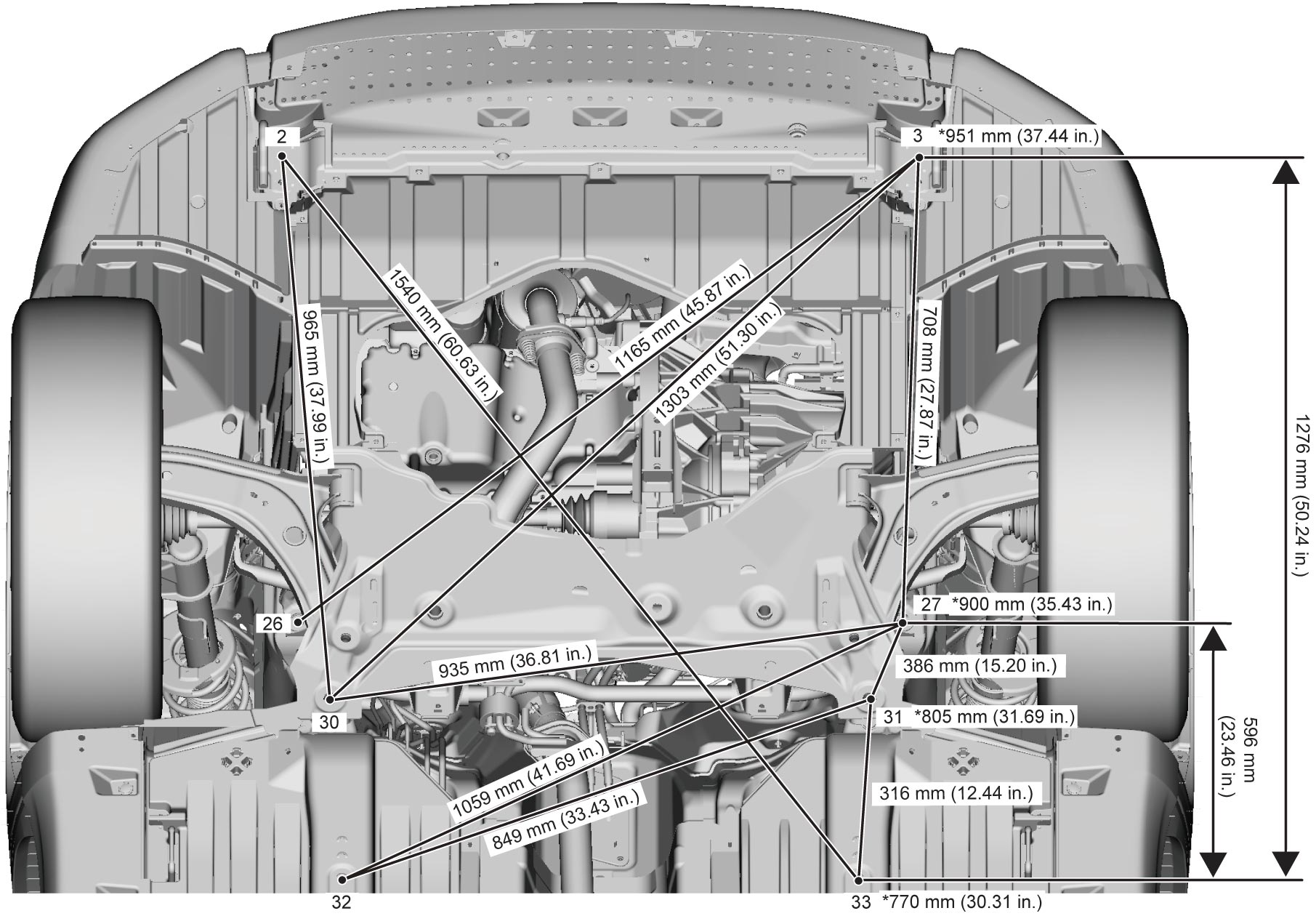
| Point | Position | ||
|---|---|---|---|
| 2 | Front lower crossmember installation bolt (front side) | R | M8 bolt head center |
| 3 | ↑ | L | ↑ |
| 26 | Suspension frame installation bolt (front side) | R | M14 bolt head center |
| 27 | ↑ | L | ↑ |
| 30 | Suspension frame installation bolt (rear side) | R | ↑ |
| 31 | ↑ | L | ↑ |
| 32 | Dash lower member jig hole | R | ø 15 hole center |
| 33 | ↑ | L | ↑ |