DTC B1191
Precautions: Precautions for Diagnosing Trouble · Precautions for Replacing Remote Controller · Precautions for Remote Controller Disposal · Precautions for Replacing Keyless Start Control Module · Precautions for Control Systems · General safety (00)
DTC Detecting Condition and Trouble Area
| DTC detecting condition | Trouble area |
|---|---|
|
B1191: Accessory Relay Malfunction Inconsistency between input voltage via “ACC” fuse and ACC relay control condition continuous for longer than specified time. |
•ACC relay circuit / connector
•ACC relay •“IGN” fuse •“ACC” fuse •Keyless start control module |
Circuit Diagram
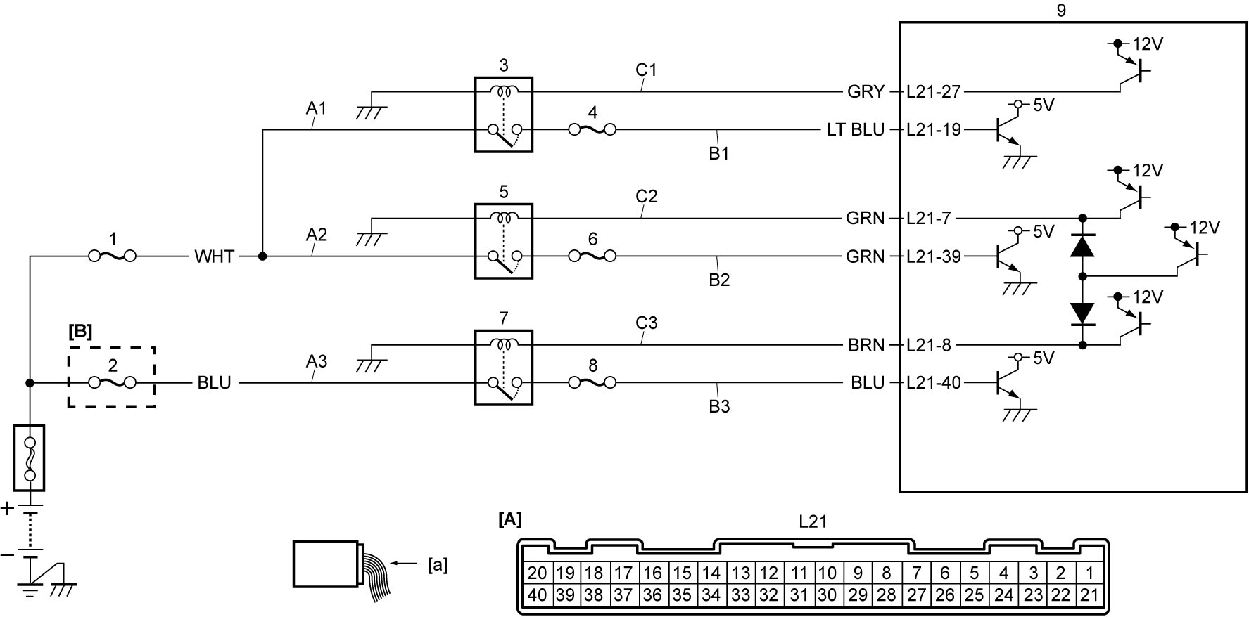
| [A]: | Keyless start control module connector (View: [a]) | B3: | IG2 relay signal circuit | 4. | “ACC” fuse |
| [B]: | D16AA model | C1: | ACC relay power supply circuit (coil side) | 5. | IG1 relay |
| A1: | ACC relay power supply circuit (switch side) | C2: | IG1 relay power supply circuit (coil side) | 6. | “MTR” fuse |
| A2: | IG1 relay power supply circuit (switch side) | C3: | IG2 relay power supply circuit (coil side) | 7. | IG2 relay |
| A3: | IG2 relay power supply circuit (switch side) | 1. | “IGN” fuse | 8. | “IG2 SIG” fuse |
| B1: | ACC relay signal circuit | 2. | “IGN2” fuse | 9. | Keyless start control module |
| B2: | IG1 relay signal circuit | 3. | ACC relay |
DTC Confirmation Procedure
1)Check that ignition is “OFF”.
2)Set ignition “ACC”.
3)Set ignition “ON”.
4)Repeat Step 1) – 3) several times.
DTC Troubleshooting
NOTE:
•This DTC might be detected when battery is run down or the voltage is very low.
•Before performing troubleshooting, remove aftermarket devices connected to the line via “ACC” fuse and devices that have a backup power supply function located in their accessory socket (non-genuine devices, optional parts, audio, etc.). Voltage from these devices may cause this DTC to be detected during diagnosis.
•Before performing troubleshooting, remove aftermarket devices connected to the line via “ACC” fuse and devices that have a backup power supply function located in their accessory socket (non-genuine devices, optional parts, audio, etc.). Voltage from these devices may cause this DTC to be detected during diagnosis.
| Step | Action | Yes | No |
|---|---|---|---|
| 1 |
ACC relay power supply circuit (switch side) check
1)Check that ignition is “OFF”.
2)Remove ACC relay.
3)Check that voltage between “A1” circuit and ground is battery voltage.
Is check result OK?
|
Go to Step 2.
|
Repair or replace defective wire harness and “IGN” fuse.
|
| 2 |
Fuse check
1)Check “ACC” fuse.
Is check result OK?
|
Go to Step 4.
|
Go to Step 3.
|
| 3 |
ACC relay signal circuit check
1)Set ignition “OFF”.
2)Disconnect “L21” connector.
3)Check for proper terminal connection to “L21” connector.
4)If connections are OK, check the following points.
•Resistance between “B1” circuit and ground: infinity
•Resistance between “B1” circuit terminal and each terminal at ACC relay connector: infinity Is check result OK?
|
Replace “ACC” fuse and keyless start control module and recheck DTC.

|
Repair or replace defective wire harness, and then replace “ACC” fuse.
|
| 4 |
ACC relay signal circuit check
1)Set ignition “OFF”.
2)Disconnect “L21” connector.
3)Check for proper terminal connection to “L21” connector.
4)If connections are OK, check the following points.
•Resistance of “B1” circuit: less than 1 Ω
•Resistance between “B1” circuit terminal and each terminal at ACC relay connector: infinity •Voltage of “B1” circuit: approx. 0 V (When ignition is “ON”) Is check result OK?
|
Go to Step 5.
|
Repair or replace defective wire harness.
|
| 5 |
ACC relay power supply circuit (coil side) check
1)Check the following points.
•Resistance of “C1” circuit: less than 1 Ω
•Resistance between “C1” circuit and ground: infinity •Resistance between “C1” circuit terminal and each terminal at ACC relay connector: infinity •Voltage of “C1” circuit: approx. 0 V (When ignition is “ON”) Is check result OK?
|
Go to Step 6.
|
Repair or replace defective wire harness.
|
| 6 |
ACC relay check
1)Check ACC relay.
Is check result OK?
|
Replace keyless start control module and recheck DTC.
|
Replace ACC relay.
|