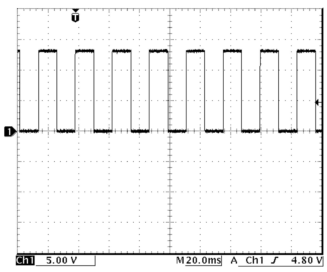
Inspection of Keyless Start Control Module and Its Circuits
Precautions: Precautions for Diagnosing Trouble · Precautions for Replacing Remote Controller · Precautions for Remote Controller Disposal · Precautions for Replacing Keyless Start Control Module · Precautions for Control Systems · General safety (00)
Voltage and Signal Check
Check voltage and/or pulse signal of keyless start control module (3) using voltmeter (1) and oscilloscope (2).
NOTE:
•Check that battery voltage is 12 V or more.
•Voltage of terminal with asterisk (*) cannot be measured by voltmeter because it is pulse signal. Check it with oscilloscope if necessary.
•Voltage of terminal with asterisk (*) cannot be measured by voltmeter because it is pulse signal. Check it with oscilloscope if necessary.
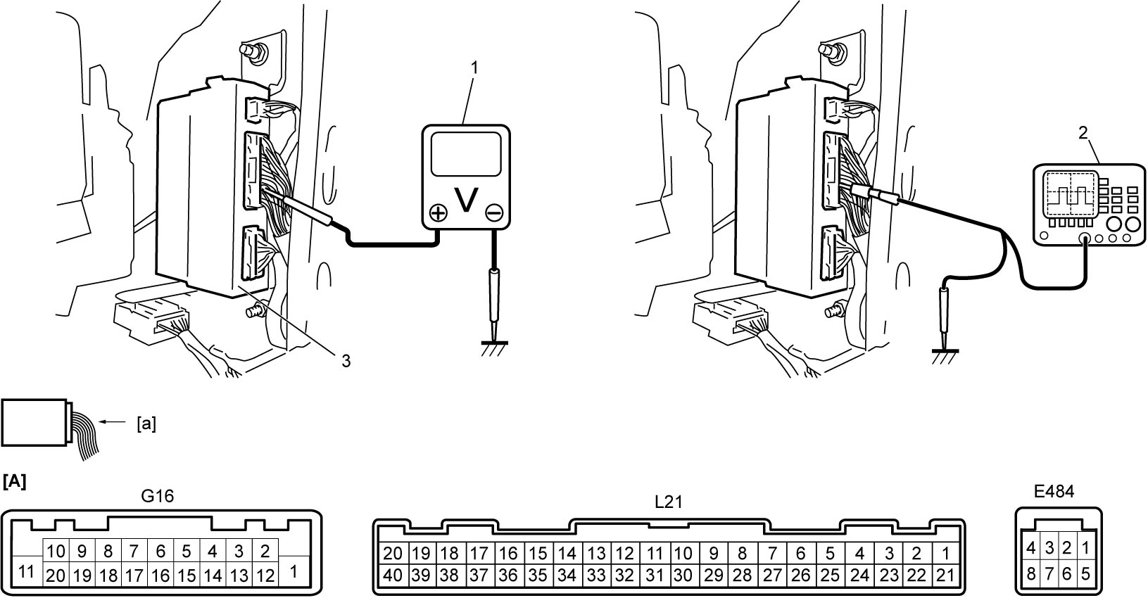
| [A]: | Keyless start control module connector (View: [a]) |
“E484” connector
| Terminal No. | Wire color | Circuit | Normal voltage | Condition |
|---|---|---|---|---|
| E484-1 | BRN | Backup power supply | 10 – 14 V | — |
| E484-2* | BLU | Hood latch switch signal (if equipped) | Refer to Hood latch switch signal, door lock switch signal, door key cylinder switch signal, rear end door switch signal, door switch signal and rear end door opener switch signal. | |
| Approx. 0 V | Hood latch: Latch released | |||
| E484-3 | RED | Horn relay | Approx. 0 V | Horn: Sounding |
| 10 – 14 V | Other than above condition | |||
| E484-4* | GRN | CPP No.1 switch signal (M/T model) | Approx. 0 V | Clutch pedal: Depressed |
| Refer to CPP No.1 switch signal and power supply for starting motor control relay (M/T model). | ||||
| Transmission range sensor signal (A/T model) | Approx. 0 V | Ignition: “ON” Select lever: P or N range |
||
| Refer to Transmission range sensor signal, power supply for starting motor control relay (A/T model) and P position switch signal. | ||||
| E484-5 | YEL | Outside warning buzzer | 0 ←→ 14 V | Outside warning buzzer: Sounding |
| E484-6 | LT GRN | Starting motor control relay signal | 10 – 14 V | Engine: Cranking |
| Approx. 0 V | Other than above condition | |||
| E484-7 | — | — | — | — |
| E484-8* | PNK | Power supply for starting motor control relay (M/T model) | 10 – 14 V | Engine: Cranking |
| Refer to CPP No.1 switch signal and power supply for starting motor control relay (M/T model). | ||||
| Power supply for starting motor control relay (A/T model) | 10 – 14 V | Engine: Cranking | ||
| Refer to Transmission range sensor signal, power supply for starting motor control relay (A/T model) and P position switch signal. | ||||
| Power supply for starting motor control relay (twin clutch system model) | 10 – 14 V | Engine: Cranking | ||
| Approx. 0 V | Other than above condition | |||
“G16” connector
| Terminal No. | Wire color | Circuit | Normal voltage | Condition |
|---|---|---|---|---|
| G16-1 | BLU | Power supply for steering lock unit | 10 – 14 V | — |
| G16-2 | YEL | Steering lock unit | — | — |
| G16-3 | — | — | — | — |
| G16-4 | PNK | Push switch 1 signal | Approx. 0 V | Engine switch: Pushed |
| 10 – 14 V | Other than above condition | |||
| G16-5 | BRN | Steering lock unit | — | — |
| G16-6 | YEL | Engine switch | — | — |
| G16-7 | GRN | Engine switch | — | — |
| G16-8 | — | — | — | — |
| G16-9* | RED | CAN communication line (high) | Refer to CAN communication signal. | |
| G16-10 | LT GRN | Steering lock unit | — | — |
| G16-11 | GRN | Steering lock unit | — | — |
| G16-12 | — | — | — | — |
| G16-13 | BLK | Engine switch | — | — |
| G16-14 | GRY | Ground for keyless start control module | Approx. 0 V | — |
| G16-15 | RED | Push switch 2 signal | Approx. 0 V | Engine switch: Pushed |
| 10 – 14 V | Other than above condition | |||
| G16-16 | LT GRN | Theft deterrent light signal | 0 ←→ 14 V | Theft deterrent light: Blinking |
| 10 – 14 V | Other than above condition | |||
| G16-17 | GRY | Engine switch | — | — |
| G16-18 | BLU | Engine switch illumination signal | Approx. 0 V | Engine switch illumination: Lit |
| 10 – 14 V | Engine switch illumination: Not lit | |||
| G16-19* | WHT | CAN communication line (low) | Refer to CAN communication signal. | |
| G16-20 | — | — | — | — |
“L21” connector
| Terminal No. | Wire color | Circuit | Normal voltage | Condition |
|---|---|---|---|---|
| L21-1* | BLK | Mid inside antenna (+) signal | Refer to Mid inside antenna signal. | |
| L21-2* | LT GRN | Rear inside antenna (+) signal | Refer to Rear inside antenna signal. | |
| L21-3* | WHT | Rear outside antenna (+) signal | Refer to Rear outside antenna signal. | |
| L21-4* | GRN | Driver side outside antenna (+) signal | Refer to Driver side outside antenna signal and passenger side outside antenna signal. | |
| L21-5* | BRN | Passenger side outside antenna (+) signal | Refer to Driver side outside antenna signal and passenger side outside antenna signal. | |
| L21-6* | PPL | Vehicle speed signal | Refer to Vehicle speed signal. | |
| L21-7 | GRN | Power supply for IG1 relay | 10 – 14 V | Ignition: “ON” |
| Approx. 0 V | Other than above condition | |||
| L21-8 | BRN | Power supply for IG2 relay | 10 – 14 V | Ignition: “ON” |
| Approx. 0 V | Other than above condition | |||
| L21-9* | BEG | Driver door lock switch signal | Refer to Hood latch switch signal, door lock switch signal, door key cylinder switch signal, rear end door switch signal, door switch signal and rear end door opener switch signal. | |
| Approx. 0 V | Driver door lock switch: Unlocked | |||
| L21-10 | RED | Passenger door request switch signal | Approx. 0 V | Passenger door request switch: Pushed |
| 10 – 14 V | Other than above condition | |||
| L21-11 | PPL | Driver door request switch signal | Approx. 0 V | Driver door request switch: Pushed |
| 10 – 14 V | Other than above condition | |||
| L21-12 | — | — | — | — |
| L21-13* | BRN | Door key cylinder switch signal (Unlock) | Refer to Hood latch switch signal, door lock switch signal, door key cylinder switch signal, rear end door switch signal, door switch signal and rear end door opener switch signal. | |
| Approx. 0 V | Door key cylinder switch: Unlocked | |||
| L21-14* | GRN | Rear end door switch signal | Refer to Hood latch switch signal, door lock switch signal, door key cylinder switch signal, rear end door switch signal, door switch signal and rear end door opener switch signal. | |
| Approx. 0 V | Rear end door: Opened | |||
| L21-15* | BLU | Rear door switch signal (R) | Refer to Hood latch switch signal, door lock switch signal, door key cylinder switch signal, rear end door switch signal, door switch signal and rear end door opener switch signal. | |
| Approx. 0 V | Rear door (R): Opened | |||
| L21-16* | PNK | Driver door switch signal | Refer to Hood latch switch signal, door lock switch signal, door key cylinder switch signal, rear end door switch signal, door switch signal and rear end door opener switch signal. | |
| Approx. 0 V | Driver door: Opened | |||
| L21-17 | — | — | — | — |
| L21-18* | BLU | Door key cylinder switch signal (Lock) | Refer to Hood latch switch signal, door lock switch signal, door key cylinder switch signal, rear end door switch signal, door switch signal and rear end door opener switch signal. | |
| Approx. 0 V | Door key cylinder switch: Locked | |||
| L21-19 | LT BLU | ACC relay signal | 10 – 14 V | Ignition: “ACC” or “ON” |
| Approx. 0 V | Other than above condition | |||
| L21-20 | RED | Backup power supply | 10 – 14 V | — |
| L21-21* | GRN | Mid inside antenna (–) signal | Refer to Mid inside antenna signal. | |
| L21-22* | RED | Rear inside antenna (–) signal | Refer to Rear inside antenna signal. | |
| L21-23* | BLU | Rear outside antenna (–) signal | Refer to Rear outside antenna signal. | |
| L21-24* | BEG | Driver side outside antenna (–) signal | Refer to Driver side outside antenna signal and passenger side outside antenna signal. | |
| L21-25* | LT GRN | Passenger side outside antenna (–) signal | Refer to Driver side outside antenna signal and passenger side outside antenna signal. | |
| L21-26 | — | — | — | — |
| L21-27 | GRY | Power supply for ACC relay | 10 – 14 V | Ignition: “ACC” or “ON” |
| Approx. 0 V | Other than above condition | |||
| L21-28 | — | — | — | — |
| L21-29* | LT BLU | Passenger door lock switch signal | Refer to Hood latch switch signal, door lock switch signal, door key cylinder switch signal, rear end door switch signal, door switch signal and rear end door opener switch signal. | |
| Approx. 0 V | Passenger door lock switch: Unlocked | |||
| L21-30 | YEL | Rear end door request switch signal | Approx. 0 V | Rear end door request switch: Pushed |
| 10 – 14 V | Other than above condition | |||
| L21-31 | — | — | — | — |
| L21-32 | — | — | — | — |
| L21-33* | PPL | CPP No.2 switch signal (M/T model) | Approx. 0 V | Ignition: “ON” Clutch pedal: Depressed |
| 10 – 14 V | Ignition: “ON” Clutch pedal: Released |
|||
| P position switch signal (A/T model / twin clutch system model) | Approx. 0 V | Ignition: “ON” Select lever: P range |
||
| Refer to Transmission range sensor signal, power supply for starting motor control relay (A/T model) and P position switch signal. | ||||
| L21-34* | WHT | Rear door switch signal (L) | Refer to Hood latch switch signal, door lock switch signal, door key cylinder switch signal, rear end door switch signal, door switch signal and rear end door opener switch signal. | |
| Approx. 0 V | Rear door (L): Opened | |||
| L21-35* | RED | Passenger door switch signal | Refer to Hood latch switch signal, door lock switch signal, door key cylinder switch signal, rear end door switch signal, door switch signal and rear end door opener switch signal. | |
| Approx. 0 V | Passenger door: Opened | |||
| L21-36 | BLK | Ground for keyless start control module | Approx. 0 V | — |
| L21-37* | LT GRN | Rear end door opener switch | Refer to Hood latch switch signal, door lock switch signal, door key cylinder switch signal, rear end door switch signal, door switch signal and rear end door opener switch signal. | |
| Approx. 0 V | Rear end opener switch: Pushed | |||
| L21-38 | GRY | Brake light switch signal | Approx. 0 V | Brake pedal: Released |
| 10 – 14 V | Brake pedal: Depressed | |||
| L21-39 | GRN | IG1 relay signal | 10 – 14 V | Ignition: “ON” |
| Approx. 0 V | Other than above condition | |||
| L21-40 | BLU | IG2 relay signal | 10 – 14 V | Ignition: “ON” |
| Approx. 0 V | Other than above condition | |||
Reference Waveform
Oscilloscope display
Shown below is typical waveform display provided by oscilloscope.
NOTE:
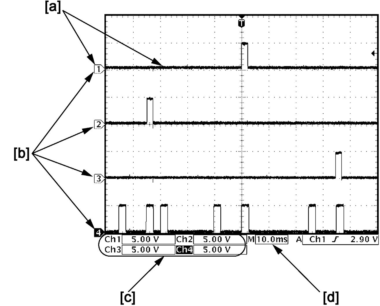

•How to read waveforms is shown below.
| [a]: | Waveform of channel 1 | [c]: | VOLT/DIV of each channel |
| [b]: | Ground level of each channel | [d]: | TIME/DIV |
•Waveform varies depending on measurement condition and vehicle spec.
Hood latch switch signal, door lock switch signal, door key cylinder switch signal, rear end door switch signal, door switch signal and rear end door opener switch signal
Hood latch switch signal
| Channel | Probe | Terminal No. |
|---|---|---|
| 1 | + | E484-2 |
| – | G16-14 |
Measurement condition
•Hood latch: Fully latched
Driver door lock switch signal
| Channel | Probe | Terminal No. |
|---|---|---|
| 1 | + | L21-9 |
| – | G16-14 |
Measurement condition
•Driver door lock switch: Locked
Door key cylinder switch (Unlock) signal
| Channel | Probe | Terminal No. |
|---|---|---|
| 1 | + | L21-13 |
| – | G16-14 |
Measurement condition
•Door key cylinder switch (Unlock): OFF
Rear end door switch signal
| Channel | Probe | Terminal No. |
|---|---|---|
| 1 | + | L21-14 |
| – | G16-14 |
Measurement condition
•Rear end door: Closed
Rear door switch signal (R)
| Channel | Probe | Terminal No. |
|---|---|---|
| 1 | + | L21-15 |
| – | G16-14 |
Measurement condition
•Rear door (R): Closed
Driver door switch signal
| Channel | Probe | Terminal No. |
|---|---|---|
| 1 | + | L21-16 |
| – | G16-14 |
Measurement condition
•Driver door: Closed
Door key cylinder switch (Lock) signal
| Channel | Probe | Terminal No. |
|---|---|---|
| 1 | + | L21-18 |
| – | G16-14 |
Measurement condition
•Door key cylinder switch (Lock): OFF
Passenger door lock switch signal
| Channel | Probe | Terminal No. |
|---|---|---|
| 1 | + | L21-29 |
| – | G16-14 |
Measurement condition
•Passenger door lock switch: Locked
Rear door switch signal (L)
| Channel | Probe | Terminal No. |
|---|---|---|
| 1 | + | L21-34 |
| – | G16-14 |
Measurement condition
•Rear door (L): Closed
Passenger door switch signal
| Channel | Probe | Terminal No. |
|---|---|---|
| 1 | + | L21-35 |
| – | G16-14 |
Measurement condition
•Passenger door: Closed
Rear end door opener switch signal
| Channel | Probe | Terminal No. |
|---|---|---|
| 1 | + | L21-37 |
| – | G16-14 |
Measurement condition
•Rear end door opener switch: Released
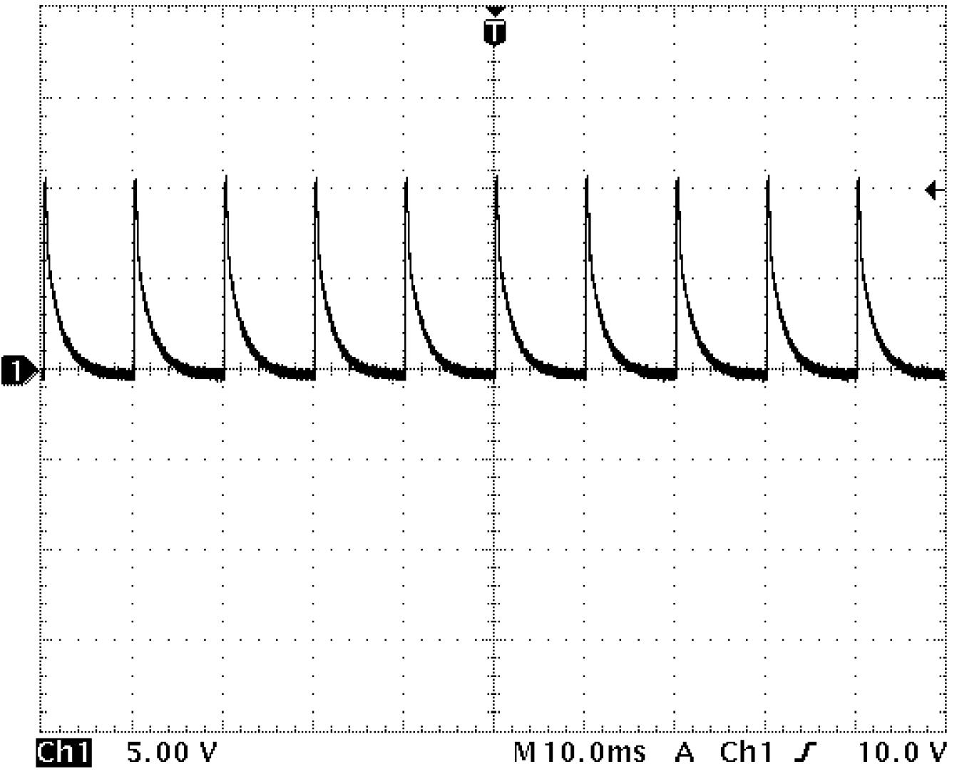
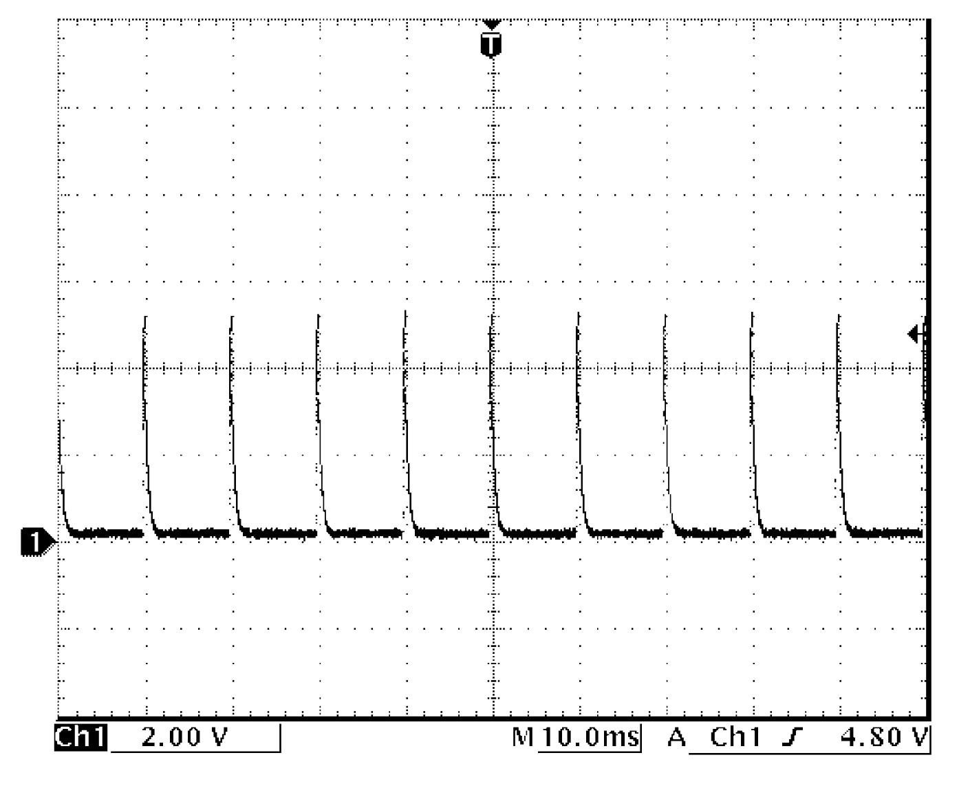
CPP No.1 switch signal and power supply for starting motor control relay (M/T model)
CPP No.1 switch signal
| Channel | Probe | Terminal No. |
|---|---|---|
| 1 | + | E484-4 |
| – | G16-14 |
Measurement condition
•Ignition: “OFF”
•Clutch pedal: Released
•Clutch pedal: Released
Power supply for starting motor control relay (M/T model)
| Channel | Probe | Terminal No. |
|---|---|---|
| 1 | + | E484-8 |
| – | G16-14 |
Measurement condition
•Ignition: “OFF”
Transmission range sensor signal, power supply for starting motor control relay (A/T model) and P position switch signal
Transmission range sensor signal
| Channel | Probe | Terminal No. |
|---|---|---|
| 1 | + | E484-4 |
| – | G16-14 |
Measurement condition
•Ignition: “ON”
•Select lever: Other than P or N range
•Select lever: Other than P or N range
Power supply for starting motor control relay (A/T model)
| Channel | Probe | Terminal No. |
|---|---|---|
| 1 | + | E484-8 |
| – | G16-14 |
Measurement condition
•Ignition: “OFF”
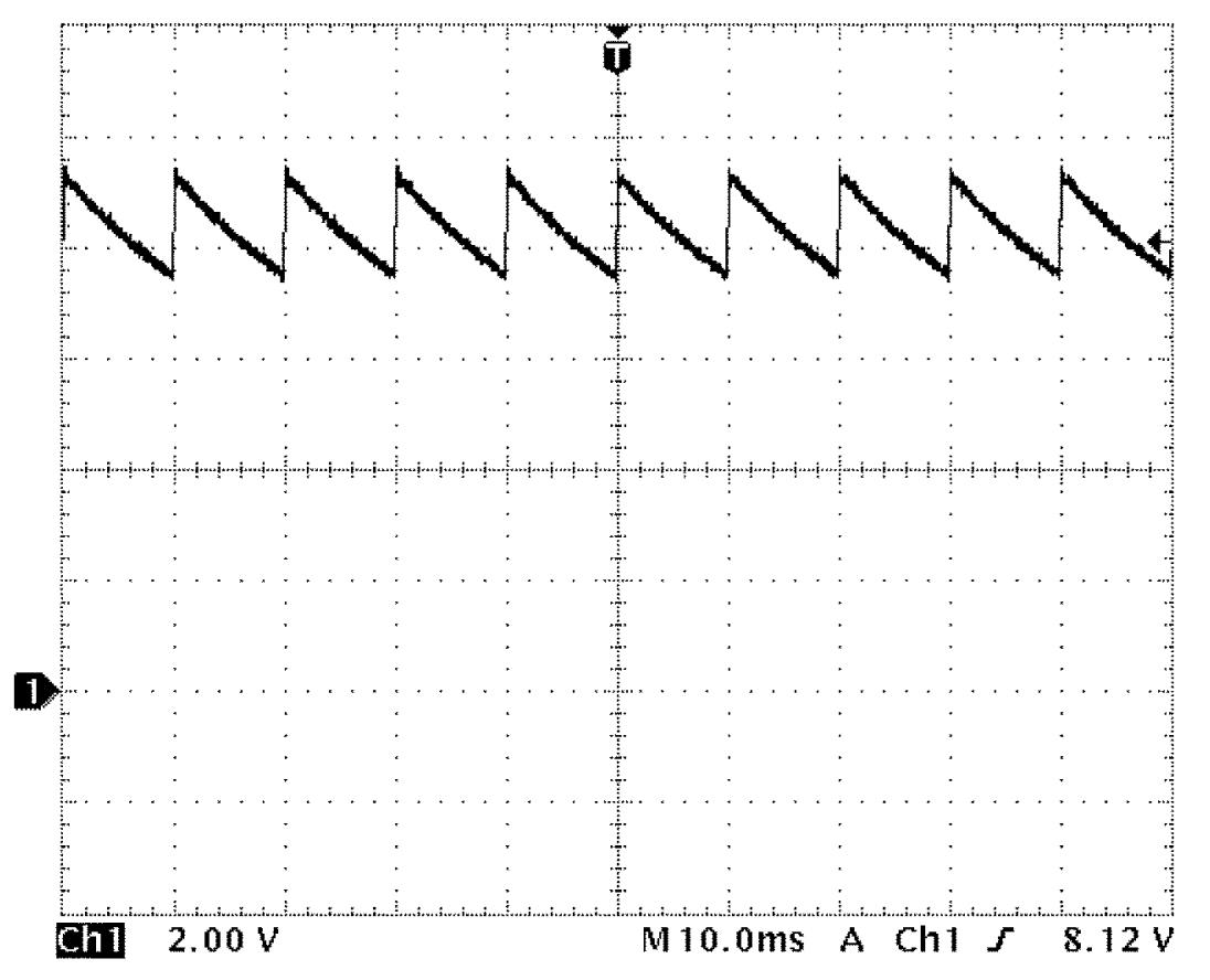
P position switch signal
| Channel | Probe | Terminal No. |
|---|---|---|
| 1 | + | L21-33 |
| – | G16-14 |
Measurement condition
•Ignition: “ON”
•Select lever: Other than P range
•Select lever: Other than P range
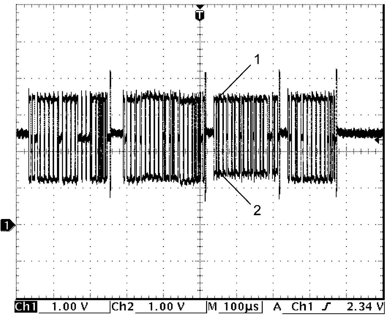
CAN communication signal
CAN communication signal (High) (1)
| Channel | Probe | Terminal No. |
|---|---|---|
| 1 | + | G16-9 |
| – | G16-14 |
CAN communication signal (Low) (2)
| Channel | Probe | Terminal No. |
|---|---|---|
| 2 | + | G16-19 |
| – | G16-14 |
Measurement condition
•Ignition: “ON”
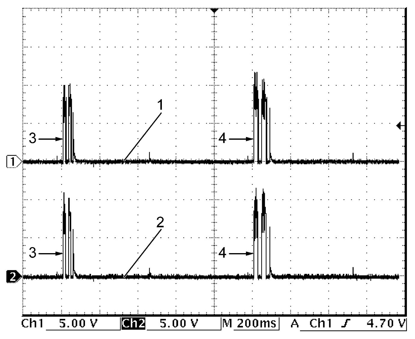
Mid inside antenna signal
Mid inside antenna (+) signal (1)
| Channel | Probe | Terminal No. |
|---|---|---|
| 1 | + | L21-1 |
| – | G16-14 |
Mid inside antenna (–) signal (2)
| Channel | Probe | Terminal No. |
|---|---|---|
| 2 | + | L21-21 |
| – | G16-14 |
Measurement condition
•Ignition: “OFF”
•All door: Closed
•Remote controller: Within driver side outside antenna detection range
•Driver door request switch: ON
•All door: Closed
•Remote controller: Within driver side outside antenna detection range
•Driver door request switch: ON
| 3. | Unlock | 4. | Lock |
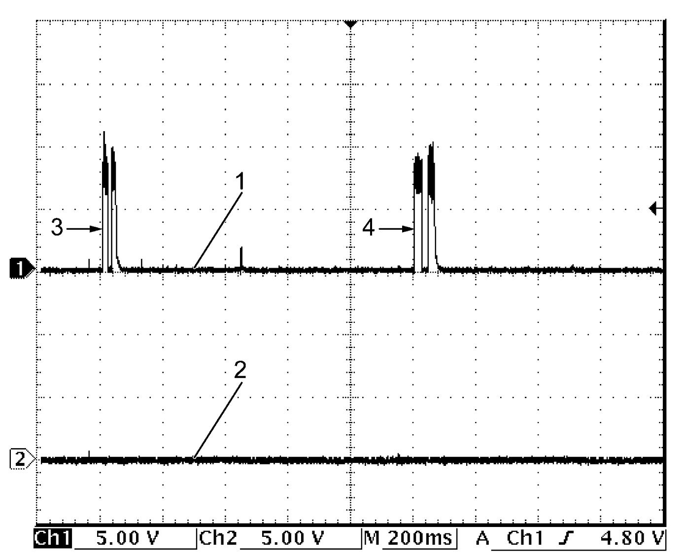
Rear inside antenna signal
Rear inside antenna (+) signal (1)
| Channel | Probe | Terminal No. |
|---|---|---|
| 1 | + | L21-2 |
| – | G16-14 |
Rear inside antenna (–) signal (2)
| Channel | Probe | Terminal No. |
|---|---|---|
| 2 | + | L21-22 |
| – | G16-14 |
Measurement condition
•Ignition: “OFF”
•All door: Closed
•Remote controller: Within driver side outside antenna detection range
•Driver door request switch: ON
•All door: Closed
•Remote controller: Within driver side outside antenna detection range
•Driver door request switch: ON
| 3. | Unlock | 4. | Lock |
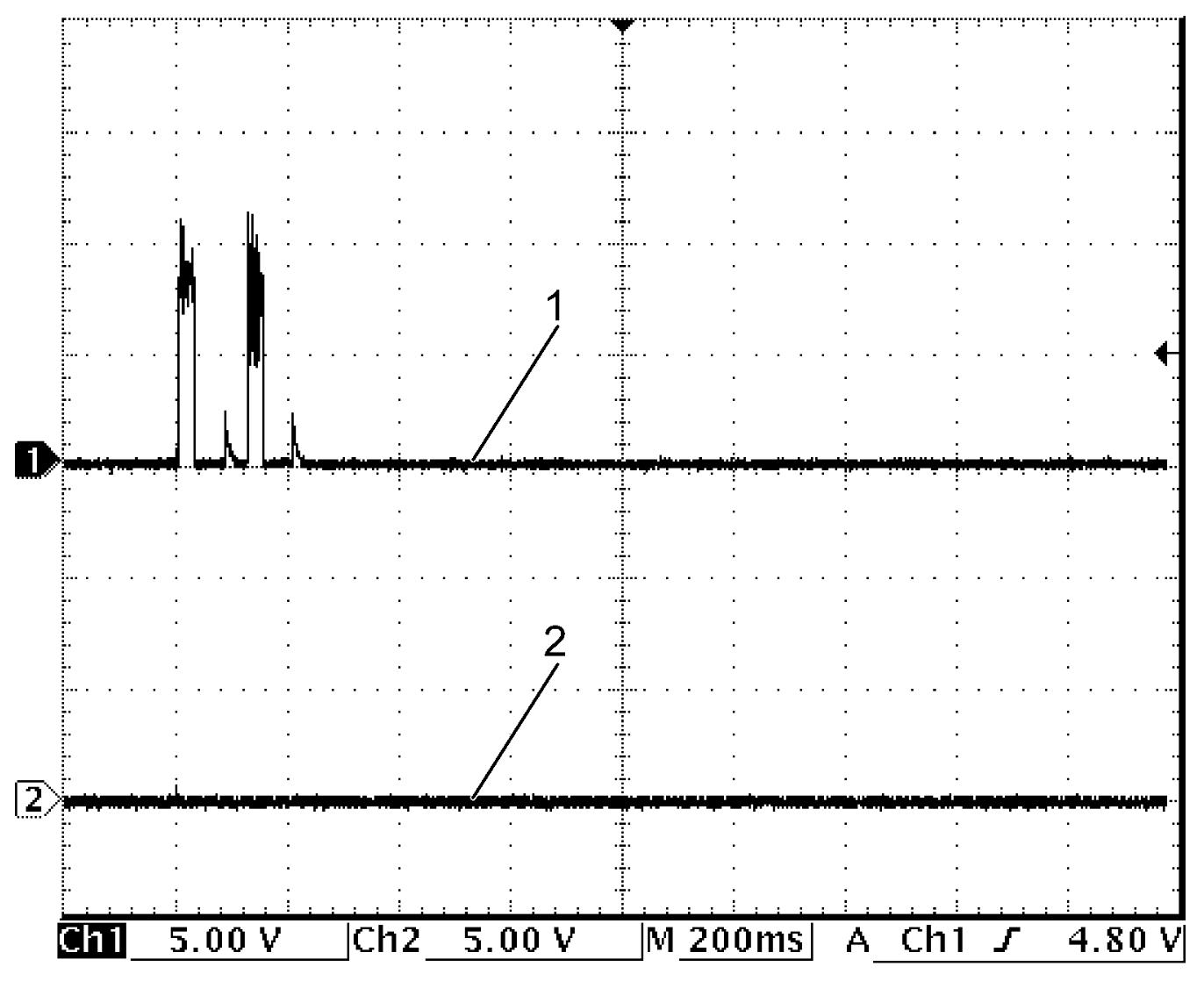
Rear outside antenna signal
Rear outside antenna (+) signal (1)
| Channel | Probe | Terminal No. |
|---|---|---|
| 1 | + | L21-3 |
| – | G16-14 |
Rear outside antenna (–) signal (2)
| Channel | Probe | Terminal No. |
|---|---|---|
| 2 | + | L21-23 |
| – | G16-14 |
Measurement condition
•Ignition: “OFF”
•All door: Closed
•Remote controller: Within rear outside antenna detection range
•Rear end door request switch: ON
•All door: Closed
•Remote controller: Within rear outside antenna detection range
•Rear end door request switch: ON
Driver side outside antenna signal and passenger side outside antenna signal
Driver side outside antenna (+) signal (1)
| Channel | Probe | Terminal No. |
|---|---|---|
| 1 | + | L21-4 |
| – | G16-14 |
Driver side outside antenna (–) signal (2)
| Channel | Probe | Terminal No. |
|---|---|---|
| 2 | + | L21-24 |
| – | G16-14 |
Measurement condition
•Ignition: “OFF”
•All door: Closed
•Remote controller: Within driver side outside antenna detection range
•Driver door request switch: ON
•All door: Closed
•Remote controller: Within driver side outside antenna detection range
•Driver door request switch: ON
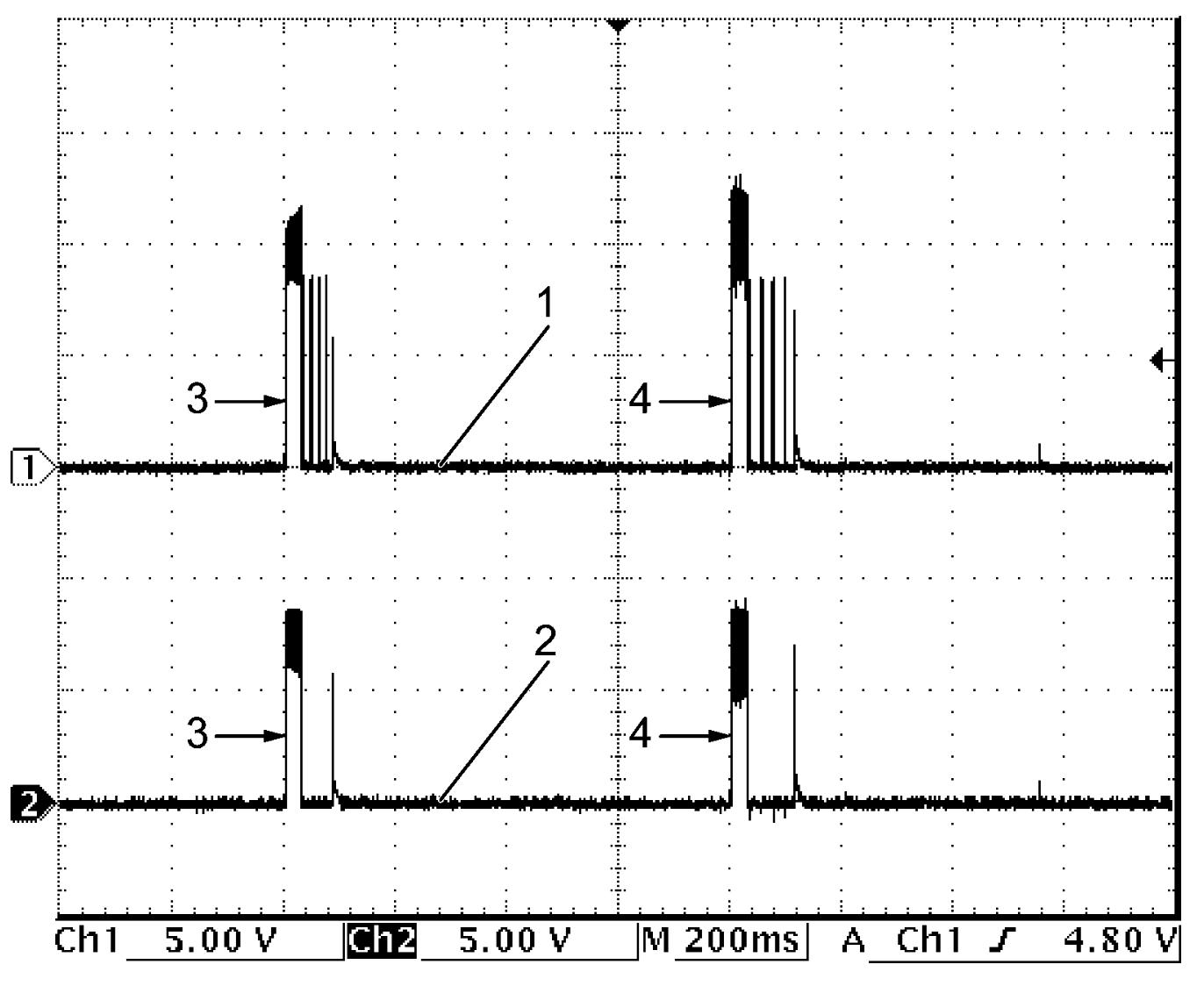
Passenger side outside antenna (+) signal (1)
| Channel | Probe | Terminal No. |
|---|---|---|
| 1 | + | L21-5 |
| – | G16-14 |
Passenger side outside antenna (–) signal (2)
| Channel | Probe | Terminal No. |
|---|---|---|
| 2 | + | L21-25 |
| – | G16-14 |
Measurement condition
•Ignition: “OFF”
•All door: Closed
•Remote controller: Within passenger side outside antenna detection range
•Passenger door request switch: ON
•All door: Closed
•Remote controller: Within passenger side outside antenna detection range
•Passenger door request switch: ON
| 3. | Unlock | 4. | Lock |
Vehicle speed signal
| Channel | Probe | Terminal No. |
|---|---|---|
| 1 | + | L21-6 |
| – | G16-14 |
Measurement condition
•Vehicle speed: 40 km/h (25 mile/h)