Home › BRAKE › BRAKE CONTROL › VEHICLE STABILITY CONTROL SYSTEM

DTC    C1210/36    Zero Point Calibration of Yaw Rate Sensor Undone

DTC    C1336/39    Zero Point Calibration of Acceleration Sensor Undone

for Preparation Click here


DESCRIPTION

The skid control ECU receives signals from the yaw rate and acceleration sensor via the CAN communication system.
The yaw rate sensor has a built-in acceleration sensor.
If there is trouble in the bus lines between the yaw rate and acceleration sensor and the CAN communication system, the DTC U0123/62 (yaw rate sensor communication trouble) and U0124/95 (acceleration sensor communication trouble) are output.
These DTCs are also output when the calibration has not been completed.

DTC No.
DTC Detection Condition
Trouble Area
C1210/36
When either of the following conditions is detected:
  1. When battery terminal was connected, shift lever was moved to non-P position within 15 seconds after ECU terminal IG1 became ON first.
  2. When the yaw rate sensor zero point recorded in ECU is deleted.
  1. Yaw rate and acceleration sensor
  2. Zero point calibration undone
  3. Park/Neutral position switch (P) circuit
C1336/39
When either of the following conditions is detected:
  1. In test mode, shift lever is shifted to non-P position 2 seconds after ECU terminal IG1 is turned ON first.
  2. When acceleration sensor zero point recorded in ECU is deleted.
  1. Yaw rate and acceleration sensor
  2. Zero point calibration undone
  3. Park/Neutral position switch (P) circuit

HINT:
If these codes (C1210/36 and/or C1336/39) are output, the following situations will occur.
  1. The VSC TRAC warning light and the VSC OFF and SLIP indicator lights will come on.
  2. Control of all systems other than ABS, EBD, and BA is canceled.


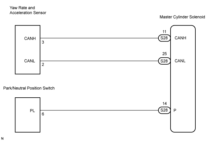
WIRING DIAGRAM


C132915E02


INSPECTION PROCEDURE

NOTICE:
When replacing the master cylinder solenoid, perform zero point calibration (Click here).

HINT:
When U0073/94, U0100/65, U0123/62, U0124/95 or U0126/63 is output together with C1210/36 or C1336/39, inspect and repair the trouble areas indicated by U0073/94, U0100/65, U0123/62, U0124/95 or U0126/63 first.

1.PERFORM ZERO POINT CALIBRATION OF YAW RATE AND ACCELERATION SENSOR

NEXT


2.RECONFIRM DTC
  1. Clear the DTCs (Click here).

  1. Check if the same DTCs are detected. (Click here).

    Result:

    Condition
    Proceed to
    DTC is output
    A
    DTC is not output
    B

    HINT:
    The DTCs are recorded because zero point calibration has not been completed.
    End the procedure since the same DTCs are not recorded after completion of the zero point calibration.


B
END
A


3.CHECK SENSOR INSTALLATION
  1. Check that the yaw rate and acceleration sensor has been installed properly.

    OK:
    The sensor should be tightened to the specified torque.
    The sensor should not be tilted.


NG
INSTALL YAW RATE AND ACCELERATION SENSOR CORRECTLY
OK


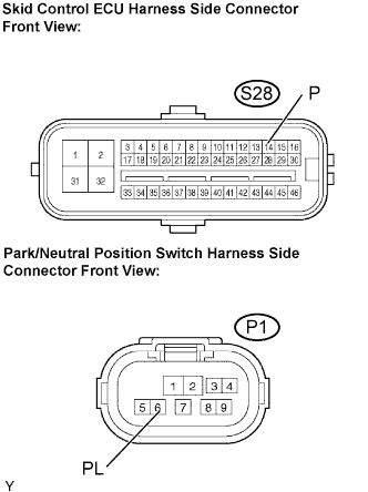
4.CHECK HARNESS AND CONNECTOR (SKID CONTROL ECU - PARK/NEUTRAL POSITION SWITCH)


    F052381E04
  1. Disconnect the skid control ECU connector and Park/Neutral position switch connector.

  1. Measure the resistance according to the value(s) in the table below.

    Standard resistance:
    Tester Connection
    Specified Condition
    S28-14 (P) - P1-6 (PL)
    Below 1 Ω
    S28-14 (P) - Body ground
    10 kΩ or higher


NG
REPAIR OR REPLACE HARNESS OR CONNECTOR
OK


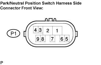
5.INSPECT PARK/NEUTRAL POSITION SWITCH ASSEMBLY


    C124790E05
  1. Measure the resistance according to the value(s) in the table below.

    Standard resistance:
    Tester Connection
    Condition
    Specified Condition
    2 - 6, 4 - 5
    P
    Below 1 Ω
    1 - 2
    R
    Below 1 Ω
    2 - 9, 4 - 5
    N
    Below 1 Ω
    2 - 7
    D, 4
    Below 1 Ω
    2 - 3
    3
    Below 1 Ω
    2 - 8
    2, L
    Below 1 Ω


NG
REPLACE PARK/NEUTRAL POSITION SWITCH ASSEMBLY
OK


6.REPLACE YAW RATE AND ACCELERATION SENSOR
  1. Replace the yaw rate and acceleration sensor (Click here).


NEXT


7.PERFORM ZERO POINT CALIBRATION OF YAW RATE AND ACCELERATION SENSOR

NEXT


8.RECONFIRM DTC
  1. Clear the DTCs (Click here).

  1. Check if the same DTCs are detected (Click here).

    HINT:
    Reinstall the sensors, connectors, etc. and restore the previous vehicle conditions before rechecking for DTCs.


    Result:

    Condition
    Proceed to
    DTC is output
    A
    DTC is not output
    B


B
END
A

REPLACE MASTER CYLINDER SOLENOID