Home › SUSPENSION & AXLE › SUSPENSION CONTROL › AIR SUSPENSION SYSTEM

AIR SUSPENSION SYSTEM > TEST MODE PROCEDURE

for Preparation Click here


INPUT SIGNAL CHECK (Using SST check wire)

HINT:
  1. This function checks if signals from the stop light switch assembly and the door courtesy light switch, etc. are being input normally to the ECU.
  2. When entering test mode, the suspension control ECU sets all the test mode DTCs first.
    After completing the test mode for each check item, the test mode DTCs that are determined normal by the suspension control ECU will be erased.
    The test mode DTCs for other check items may not be erased when only a certain signal is inspected.
  3. When the test mode returns back to normal mode, all the test mode DTCs will be erased.


  1. Procedure for Input Signal Check Mode (Test Mode) using SST check wire.

    SST
    09843-18040  

    1. Make sure the ignition switch is OFF.

    2. Set each of the check items to the condition shown as Operation (A) in the test mode table.


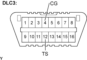
    3. F100115E29
    4. Using SST, connect terminals TS and CG of the DLC3.

    5. Turn the ignition switch to the ON position.


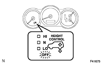
    6. F041675
    7. Check that the height control OFF indicator light is blinking.

      HINT:
      1. The height control OFF indicator light comes on for 2 seconds, then blinks at 0.25 sec. intervals.
      2. If the height control OFF indicator light does not blink, inspect the height control manual indicator light circuit (Click here) and the TS terminal circuit (Click here).

    8. Set each of the check items to the condition shown as Operation (B) in the test mode table.

      HINT:
      When checking each item, the height control OFF indicator light should comes on for 1 second.


      Test mode table:

      Check Item
      Operation (A)
      Operation (B)
      Stop light switch signal
      OFF (Brake pedal not depressed)
      ON (Brake pedal depressed)
      Door courtesy light switch signal
      ON (Each door opened)
      OFF (All doors closed)
      Height control switch signal
      -
      Press the height control switch "UP" first and then press "DOWN"
      Height control OFF switch signal
      OFF (Height control OFF switch not pushed in)
      ON to OFF (Height control OFF switch pushed in and released)
      Right front speed sensor signal
      Vehicle speed below 20 km/h (12 mph)
      Vehicle speed 20 km/h (12 mph) or higher
      Left front speed sensor signal
      Vehicle speed below 20 km/h (12 mph)
      Vehicle speed 20 km/h (12 mph) or higher
      Crankshaft position sensor signal
      Engine speed below 2,000 rpm
      Engine speed 2,000 rpm or higher


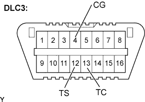
    9. F100115E28
    10. Using SST, connect the 3rd terminal of the SST check wire to terminal TC of the DLC3.

      SST
      09843-18040  


    11. F041675
    12. Read the number of blinks of the height control OFF indicator light.

      HINT:
      1. As examples, the blinking patterns of a normal system code and code 82 are shown in the illustration.
      2. If 2 or more malfunctions are indicated at the same time, the lowest numbered code is displayed first.
      3. When a DTC is not output, check the TC terminal circuit (Click here).


    13. Check the malfunction using the test mode DTC chart.
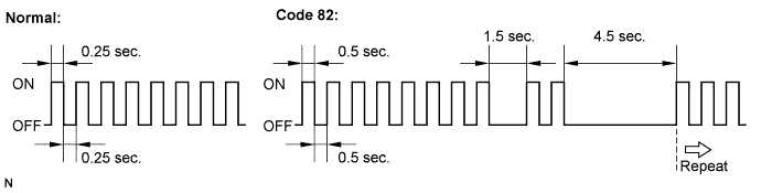

      C120690E01

  2. Ending the Input Signal Check Mode (Test Mode) using SST check wire.

    SST
    09843-18040  

    1. With the ignition switch OFF, disconnect the SST check wire from the terminals of the DLC3 and then turn the ignition switch to the ON position.

  3. Procedure for Sensor Test Mode (Test Mode) using the intelligent tester.

    1. Make sure the ignition switch is OFF.

    2. Set each of the check items to the condition shown as Operation (A) in the test mode table.

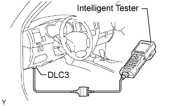
    3. Connect the intelligent tester to the DLC3.

    4. Turn the ignition switch to the ON position.

    5. Select SIGNAL CHECK mode on the intelligent tester.

    6. Set each of the check items to the condition shown as Operation (B) in the test mode table (Procedure "A").

      HINT:
      In procedure "A", all signals can be checked together.

    7. Read the DTCs by following the prompts on the tester screen.

      HINT:
      Refer to the intelligent tester operators manual for further details.

  4. DTC of air suspension system test mode (input signal check) function:
    If a trouble code is displayed during the test mode DTC check, check the circuit listed for that code. For details of each code, refer to "See page" under the respective DTC No. in the chart.

    Test Mode DTC Chart 
    DTC No.
    Detection Item
    Trouble Area
    C1782/82
    Stop light switch circuit malfunction
    1. Stop light switch assembly
    2. Stop light switch circuit
    3. Suspension control ECU
    C1783/83
    Door courtesy switch circuit malfunction
    1. Door courtesy light switch assembly
    2. Back door lock assembly (Back door courtesy light switch)
    3. Door courtesy light switch circuit
    4. Body ECU
    5. Back door ECU
    6. Suspension control ECU
    C1786/86
    Height control switch circuit malfunction
    1. Height control switch
    2. Height control switch circuit
    3. Suspension control ECU
    C1788/88
    Height control OFF switch circuit malfunction
    1. Height control OFF switch (Suspension control switch)
    2. Height control OFF switch circuit
    3. Suspension control ECU
    C1794/94
    Right front speed sensor circuit malfunction
    1. Right front speed sensor
    2. Right front speed sensor circuit
    3. Skid control ECU assembly
    4. Suspension control ECU
    C1795/95
    Left front speed sensor circuit malfunction
    1. Left front speed sensor
    2. Left front speed sensor circuit
    3. Skid control ECU assembly
    4. Suspension control ECU
    C1797/97
    Crankshaft position sensor circuit malfunction
    1. Crankshaft position sensor
    2. Crankshaft position sensor circuit
    3. ECM
    4. Suspension control ECU


INPUT SIGNAL CHECK (Using INTELLIGENT TESTER)

HINT:
  1. This function checks if signals from the stop light switch assembly and the door courtesy light switch, etc. are being input normally to the ECU.
  2. When entering test mode, the suspension control ECU sets all the test mode DTCs first.
    After completing the test mode for each check item, the test mode DTCs that are determined normal by the suspension control ECU will be erased.
    The test mode DTCs for other check items may not be erased when only a certain signal is inspected.
  3. When the test mode returns back to normal mode, all the test mode DTCs will be erased.


    A066288E03
  1. Procedure for Test Mode (Input signal check).

    1. Make sure that the ignition switch is off.

    2. Set each of the check items to the condition shown as Operation (A) in the test mode table.

    3. Connect the intelligent tester to the DLC3.

    4. Turn the ignition switch to the ON position.

    5. Select TEST MODE mode on the intelligent tester.

    6. Set each of the check items to the condition shown as Operation (B) in the test mode table (Procedure "C").

      Test mode (input signal check) table:

      Check Item
      Operation (A)
      Operation (B)
      Stop light switch signal
      OFF (Brake pedal not depressed)
      ON (Brake pedal depressed)
      Door courtesy light switch signal
      ON (Each door opened)
      OFF (All doors closed)
      Height control switch signal
      -
      Press the height control switch "UP" first and then press "DOWN"
      Height control OFF switch signal
      OFF (Height control OFF switch not pushed in)
      ON to OFF (Height control OFF switch pushed in and released)
      Right front speed sensor signal
      Vehicle speed below 20 km/h (12 mph)
      Vehicle speed 20 km/h (12 mph) or higher
      Left front speed sensor signal
      Vehicle speed below 20 km/h (12 mph)
      Vehicle speed 20 km/h (12 mph) or higher
      Crankshaft position sensor signal
      Engine speed below 2,000 rpm
      Engine speed 2,000 rpm or higher

      HINT:
      In procedure "C", all signals can be checked together.

    7. Read the test mode DTCs by following the prompts on the tester screen.

      HINT:
      Refer to the intelligent tester operator's manual for further details.

    8. Check the malfunction using the code table below. After completing the test mode, disconnect the tester and turn the ignition switch off.

  2. DTC of air suspension system test mode (input signal check) function:
    If a trouble code is displayed during the test mode DTC check, check the circuit listed for that code. For details of each code, refer to "See page" under the respective DTC No. in the chart.

    Test Mode DTC Chart 
    DTC No.
    Detection Item
    Trouble Area
    C1782/82
    Stop light switch circuit malfunction
    1. Stop light switch assembly
    2. Stop light switch circuit
    3. Suspension control ECU
    C1783/83
    Door courtesy switch circuit malfunction
    1. Door courtesy light switch assembly
    2. Back door lock assembly (Back door courtesy light switch)
    3. Door courtesy light switch circuit
    4. Main Body ECU
    5. Back door ECU
    6. Suspension control ECU
    C1786/86
    Height control switch circuit malfunction
    1. Height control switch
    2. Height control switch circuit
    3. Suspension control ECU
    C1788/88
    Height control OFF switch circuit malfunction
    1. Height control OFF switch (Suspension control switch)
    2. Height control OFF switch circuit
    3. Suspension control ECU
    C1794/94
    Right front speed sensor circuit malfunction
    1. Right front speed sensor
    2. Right front speed sensor circuit
    3. Skid control ECU assembly
    4. Suspension control ECU
    C1795/95
    Left front speed sensor circuit malfunction
    1. Left front speed sensor
    2. Left front speed sensor circuit
    3. Skid control ECU assembly
    4. Suspension control ECU
    C1797/97
    Crankshaft position sensor circuit malfunction
    1. Crankshaft position sensor
    2. Crankshaft position sensor circuit
    3. ECM
    4. Suspension control ECU