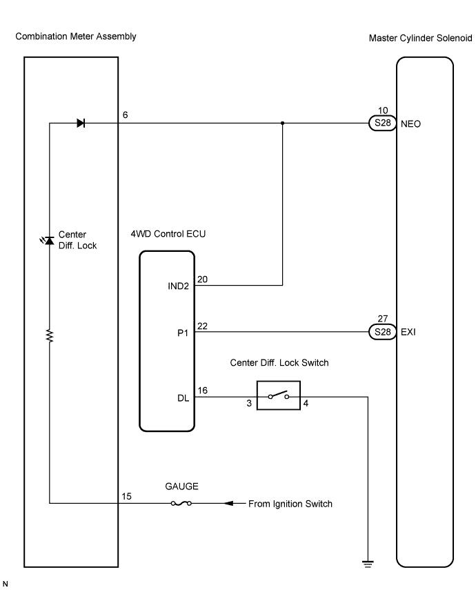
DTC C1340/47 Center Differential Lock Circuit |
| DTC No. | DTC Detection Condition | Trouble Area |
| C1340/47 |
|
|
| 1.INSPECT SKID CONTROL ECU (EXI TERMINAL) |
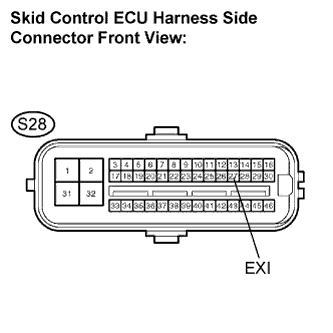 |
Transfer is in 4WD mode (Multi Mode 4WD only).
Disconnect the skid control ECU connector.
Turn the ignition switch to the ON position.
Measure the voltage according to the value(s) in the table below.
| Tester Connection | Condition | Specified Condition |
| S28-27 (EXI) - Body ground | Center diff. locked | Below 1.5 V |
| S28-27 (EXI) - Body ground | Center diff. free | 10 to 14 V |
|
| ||||
| OK | |
 |
| 2.INSPECT SKID CONTROL ECU (NEO TERMINAL) |
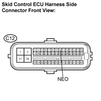 |
Measure the voltage according to the value(s) in the table below.
| Tester Connection | Condition | Specified Condition |
| S28-10 (NEO) - Body ground | Center diff. locked | Below 2 V |
| S28-10 (NEO) - Body ground | Center diff. free | 10 to 14 V |
|
| ||||
| OK | |
|
| 3.RECONFIRM DTC |
Clear the DTC (Click here).
Check if the same DTC is detected (Click here).
| Condition | Proceed to |
| DTC is output | A |
| DTC is not output | B |
|
| ||||
| A | ||
 | ||
| ||
| 4.INSPECT CENTER DIFFERENTIAL LOCK SWITCH (GROUND TERMINAL) |
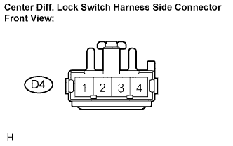 |
Disconnect the center diff. lock switch connector.
Measure the resistance according to the value(s) in the table below.
| Tester Connection | Specified Condition |
| D4-4 - Body ground | Below 1 Ω |
|
| ||||
| OK | |
|
| 5.INSPECT CENTER DIFFERENTIAL LOCK SWITCH |
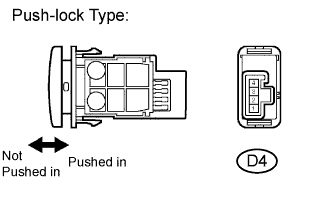 |
Measure the resistance according to the value(s) in the table below.
| Tester Connection | Condition | Specified Condition |
| D4-3 - D4-4 | Switch is pushed in | Below 1 Ω |
| D4-3 - D4-4 | Switch is not pushed in | 10 kΩ or higher |
|
| ||||
| OK | |
|
| 6.INSPECT 4WD CONTROL ECU |
Check the select high-low system (Click here) or the select 2-4 and high-low system (Click here).
|
| ||||
| OK | |
|
| 7.CHECK HARNESS AND CONNECTOR (4WD CONTROL ECU - CENTER DIFFERENTIAL LOCK SWITCH) |
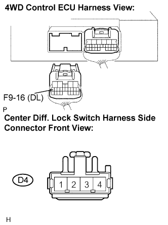 |
Disconnect the 4WD control ECU (F9) connector and center diff. lock switch connector.
Measure the resistance according to the value(s) in the table below.
| Tester Connection | Specified Condition |
| F9-16 (DL) - D4-3 | Below 1 Ω |
| F9-16 (DL) - Body ground | 10 kΩ or higher |
|
| ||||
| OK | |
|
| 8.CHECK HARNESS AND CONNECTOR (SKID CONTROL ECU - 4WD CONTROL ECU) |
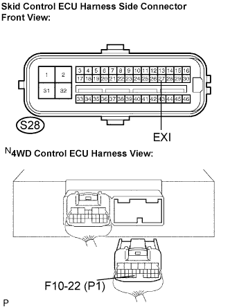 |
Disconnect the 4WD control ECU (F10) connector.
Measure the resistance according to the value(s) in the table below.
| Tester Connection | Specified Condition |
| S28-27 (EXI) - F10-22 (P1) | Below 1 Ω |
| S28-27 (EXI) - Body ground | 10 kΩ or higher |
|
| ||||
| NG | ||
| ||
| ||
| 9.CHECK HARNESS AND CONNECTOR (SKID CONTROL ECU - 4WD CONTROL ECU) |
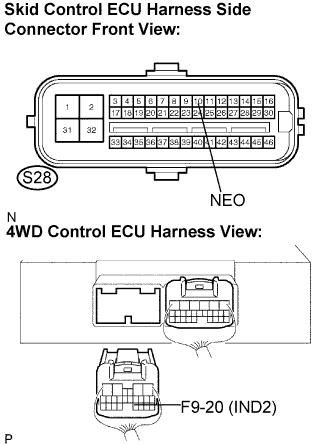 |
Disconnect the 4WD control ECU (F9) connector.
Measure the resistance according to the value(s) in the table below.
| Tester Connection | Specified Condition |
| S28-10 (NEO) - F9-20 (IND2) | Below 1 Ω |
| S28-10 (NEO) - Body ground | 10 kΩ or higher |
|
| ||||
| OK | |
|
| 10.CHECK HARNESS AND CONNECTOR (SKID CONTROL ECU - COMBINATION METER) |
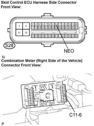 |
Disconnect the combination meter connector.
Measure the resistance according to the value(s) in the table below.
| Tester Connection | Specified Condition |
| S28-10 (NEO) - C11-6 | Below 1 Ω |
| S28-10 (NEO) - Body ground | 10 kΩ or higher |
|
| ||||
| OK | |
|
| 11.INSPECT COMBINATION METER ASSEMBLY |
Check the combination meter system (Click here).
|
| ||||
| OK | |
|
| 12.RECONFIRM DTC |
Clear the DTC (Click here).
Check if the same DTC is detected (Click here).
| Condition | Proceed to |
| DTC is output | A |
| DTC is not output | B |
|
| ||||
| A | ||
| ||
| ||

