A750E AUTOMATIC TRANSMISSION / TRANSAXLE AUTOMATIC TRANSMISSION UNIT REASSEMBLY
PROCEDURE

 1. BEARING POSITION
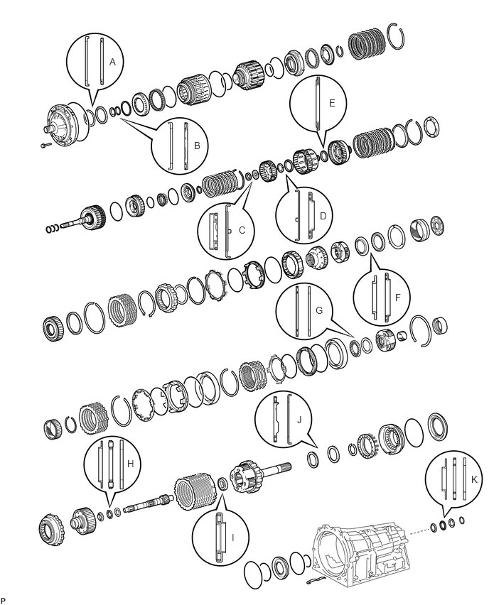
- Bearing and Race Diameter:
Mark Front Race Diameter Inside/Outside Thrust Bearing Diameter Inside/Outside Rear Race Diameter Inside/Outside A 74.3 to 74.6 mm (2.93 to 2.94 in.)/87.4 to 87.7 mm (3.44 to 3.45 in.) 72.0 to 72.3 mm (2.83 to 2.85 in.)/85.3 to 85.6 mm (3.36 to 3.37 in.) - B 37.0 to 37.3 mm (1.46 to 1.47 in.)/52.1 to 52.3 mm (2.05 to 2.06 in.) 34.7 to 34.9 mm (1.366 to 1.374 in.)/51.6 to 51.9 mm (2.03 to 2.04 in.) - C - 21.4 to 21.6 mm (0.841 to 0.850 in.)/40.8 to 41.0 mm (1.606 to 1.614 in.) 22.7 to 22.9 mm (0.892 to 0.902 in.)/60.0 to 60.4 mm (2.36 to 2.38 in.) D 33.3 to 33.5 mm (1.31 to 1.32 in.)/56.3 to 56.6 mm (2.22 to 2.23 in.) 38.5 to 38.7 mm (1.515 to 1.524 in.)/56.5 to 57.0 mm (2.22 to 2.24 in.) - E - 42.6 to 42.8 mm (1.68 to 1.69 in.)/60.8 to 61.1 mm (2.39 to 2.41 in.) - F 38.0 to 38.2 mm (1.496 to 1.504 in.)/56.5 to 57.0 mm (2.22 to 2.24 in.) 43.4 to 43.6 mm (1.71 to 1.72 in.)/58.0 to 58.4 mm (2.28 to 2.30 in.) - G - 55.8 to 56.0 mm (2.197 to 2.204 in.)/76.1 to 76.4 mm (2.996 to 3.008 in.) 53.8 to 54.0 mm (2.12 to 2.13 in.)/73.7 to 74.0 mm (2.90 to 2.91 in.) H 33.4 to 33.6 mm (1.31 to 1.32 in.)/48.7 to 49.0 mm (1.92 to 1.93 in.) 32.2 to 32.3 mm (1.268 to 1.272 in.)/49.0 to 49.2 mm (1.93 to 1.94 in.) 32.2 to 32.4 mm (1.27 to 1.28 in.)/48.7 to 49.0 mm (1.92 to 1.93 in.) I - 21.5 to 21.8 mm (0.846 to 0.858 in.)/40.5 to 40.8 mm (1.59 to 1.61 in.) - J - 43.6 to 43.9 mm (1.72 to 1.73 in.)/60.6 to 60.9 mm (2.39 to 2.40 in.) 47.2 to 47.4 mm (1.86 to 1.87 in.)/66.9 to 67.1 mm (2.63 to 2.64 in.) K 36.9 to 37.2 mm (1.45 to 1.46 in.)/49.4 to 50.0 mm (1.94 to 1.97 in.) 36.15 to 36.31 mm (1.42 to 1.43 in.)/52.06 to 52.36 mm (2.05 to 2.06 in.) 36.15 to 36.4 mm (1.42 to 1.43 in.)/50.5 to 51.0 mm (1.99 to 2.01 in.)
35629A
2.ASSEMBLE NO. 4 BRAKE PISTON AND BRAKE REACTION SLEEVE
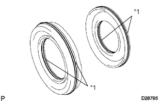
Coat 2 new O-rings with ATF and install them to the brake reaction sleeve.
Coat 2 new O-rings with ATF and install them to the No. 4 brake piston.
| *1 | New O-Ring |
Install the No. 4 brake piston to the reaction sleeve.
35626
3.INSTALL NO. 4 BRAKE PISTON WITH BRAKE REACTION SLEEVE
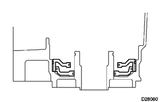
Install the No. 4 brake piston with brake reaction sleeve to the transmission case.
- NOTICE:
- ·
Do not damage the O-rings.
·Make sure the No. 4 brake piston is underneath the brake reaction sleeve.
35623H
4.INSTALL 1ST AND REVERSE BRAKE PISTON
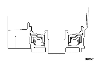
Coat a new O-ring with ATF.
Install the O-ring to the 1st and reverse brake piston.
With the spring seat of the piston facing upwards (the front side), install the piston to the transmission case.
- NOTICE:
-
Be careful not to damage the O-ring.
35068
5.INSTALL 1ST AND REVERSE BRAKE RETURN SPRING SUB-ASSEMBLY
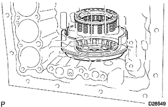
Install the brake return spring to the 1st and reverse brake piston.
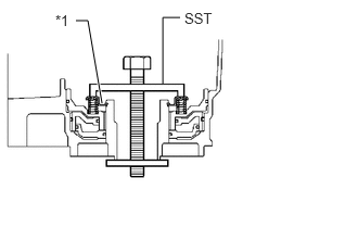
Place SST on the spring retainer and compress the return spring.
- SST
- 09350-30020 (09350-07050)
Using SST, install the snap ring.
- SST
- 09350-30020 (09350-07070)
| *1 | Snap Ring |
35719B
6.INSTALL REAR PLANETARY GEAR ASSEMBLY
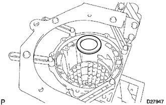
Install the No. 9 thrust bearing race.
- Thrust Bearing Race Diameter:
Item Inside Outside Race J 47.2 to 47.4 mm (1.86 to 1.87 in.) 66.9 to 67.1 mm (2.63 to 2.64 in.)
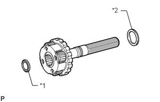
Coat the 2 thrust needle roller bearings with petroleum jelly and install them to the rear planetary gear.
- Thrust Needle Roller Bearing Diameter:
Item Inside Outside Bearing J 43.6 to 43.9 mm (1.72 to 1.73 in.) 60.6 to 60.9 mm (2.39 to 2.40 in.) Bearing I 21.5 to 21.8 mm (0.846 to 0.858 in.) 40.5 to 40.8 mm (1.59 to 1.61 in.)
| *1 | Bearing I |
| *2 | Bearing J |
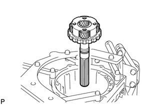
Install the rear planetary gear assembly.
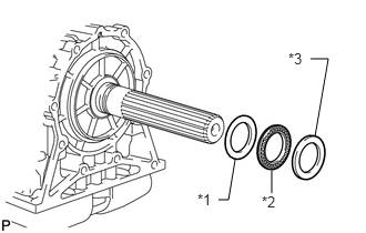
Install the rear planetary flange thrust bearing race, thrust needle roller bearing and thrust bearing selective race.
| *1 | Race K |
| *2 | Bearing K |
| *2 | Selective Race |
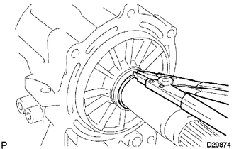
Using a snap ring expander, install the snap ring.
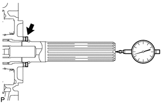
Using a dial indicator, measure the rear planetary gear end play.
- Standard end play:
0.02 to 0.12 mm (0.000787 to 0.00472 in.)
If the end play is not as specified, replace the thrust bearing race shown in the illustration with one of a different thickness so that the measured value is within the standard range.
- HINT:
-
Use the table below to select a thrust bearing race of an appropriate thickness.
- Bearing Race Thickness:
Mark Thickness 
3.775 to 3.825 mm (0.149 to 0.151 in.) 
3.825 to 3.875 mm (0.151 to 0.153 in.) 
3.875 to 3.925 mm (0.153 to 0.155 in.) 
3.925 to 3.975 mm (0.155 to 0.156 in.) 
3.975 to 4.025 mm (0.156 to 0.158 in.) 
4.025 to 4.075 mm (0.158 to 0.160 in.) 
4.075 to 4.125 mm (0.160 to 0.162 in.) 
4.125 to 4.175 mm (0.162 to 0.164 in.) 
4.175 to 4.225 mm (0.164 to 0.166 in.) 
4.225 to 4.275 mm (0.166 to 0.168 in.) 
4.275 to 4.325 mm (0.168 to 0.170 in.) 
4.325 to 4.375 mm (0.170 to 0.172 in.)
35676A
7.SELECT 1ST AND REVERSE BRAKE FLANGE
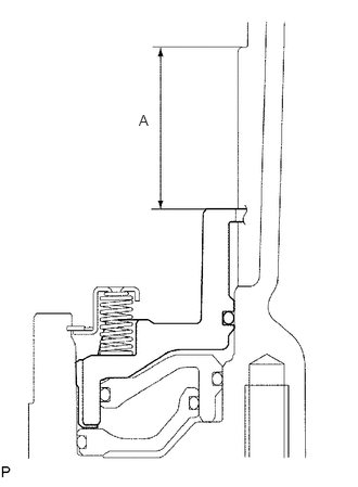
Using a vernier caliper, measure distance A (from the top surface of the 1st and reverse brake piston to the step in the transmission case) in the illustration.
- NOTICE:
-
Make sure the 1st and reverse brake piston is installed securely to the transmission case.
- HINT:
-
Distance A = 36.35 to 37.09 mm (1.43 to 1.46 in.)
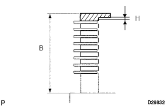
Assemble the 2 flanges, 8 discs and 7 plates, and using a vernier caliper, measure distance B in the illustration at both ends across the diameter, and calculate the average.
- HINT:
-
Distance B = 36.04 to 37.14 mm (1.42 to 1.46 in.)
Select a 1st and reverse brake flange so that the value of measured distance A minus distance B is 2.85 to 3.15 mm (0.112 to 0.124 in.).
- Flange H Thickness:
No. Thickness 0 0 mm (0 in.) 2 0.15 to 0.25 mm (0.00590 to 0.00984 in.) 4 0.35 to 0.45 mm (0.0138 to 0.0177 in.) 6 0.55 to 0.65 mm (0.0217 to 0.0256 in.) 8 0.75 to 0.85 mm (0.0295 to 0.0335 in.) 10 0.95 to 1.05 mm (0.0374 to 0.0413 in.) 12 1.15 to 1.25 mm (0.0453 to 0.0492 in.) 14 1.35 to 1.45 mm (0.0531 to 0.0571 in.)
35684
8.INSTALL NO. 4 BRAKE DISC
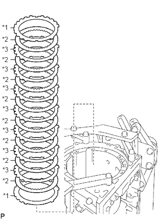
Install the 2 flanges, 8 discs and 7 plates.
- Install in order:
*1 - *2 - *3 - *2 - *3 - *2 - *3 - *2 - *3 - *2 - *3 - *2 - *3 - *2 - *3 - *2 - *1
| *1 | Flange |
| *2 | Disc |
| *3 | Plate |
35639B
9.INSTALL BRAKE PLATE STOPPER SPRING
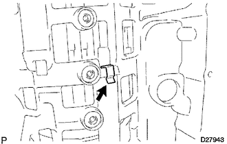
35077D
10.INSTALL REAR PLANETARY RING GEAR FLANGE SUB-ASSEMBLY
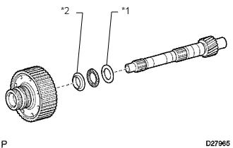
Install the thrust bearing race, thrust needle roller bearing, thrust bearing race and planetary ring gear flange to the intermediate shaft.
- Thrust Needle Roller Bearing and Race Diameter:
Item Inside Outside Race H Rear 32.2 to 32.4 mm (1.27 to 1.28 in.) 48.7 to 49.0 mm (1.92 to 1.93 in.) Bearing H 32.2 to 32.3 mm (1.268 to 1.272 in.) 49.0 to 49.2 mm (1.93 to 1.94 in.) Race H Front 33.4 to 33.6 mm (1.31 to 1.32 in.) 48.7 to 49.0 mm (1.92 to 1.93 in.)
| *1 | Race H Rear |
| *2 | Race H Front |
35770C
11.INSTALL NO. 3 1-WAY CLUTCH ASSEMBLY
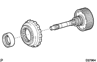
Install the 1-way clutch and 1-way clutch inner race to the intermediate shaft.
35713
12.INSTALL INTERMEDIATE SHAFT
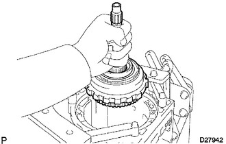
Install the intermediate shaft with No. 3 1-way clutch assembly to the case.
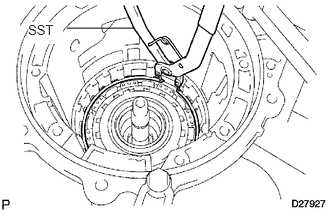
Using SST, install the snap ring.
- SST
- 09350-30020 (09350-07060)
35750
13.INSTALL CENTER PLANETARY GEAR ASSEMBLY
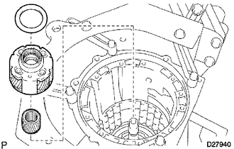
Install the planetary sun gear and center planetary gear to the case.
Coat the thrust bearing race with petroleum jelly and install it to the center planetary gear.
- Thrust Bearing Race Diameter:
Item Inside Outside Race G 53.8 to 54.0 mm (2.12 to 2.13 in.) 73.7 to 74.0 mm (2.90 to 2.91 in.)
35622G
14.INSTALL NO. 2 BRAKE PISTON
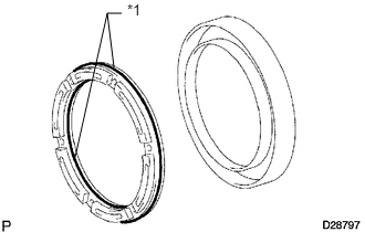
Coat 2 new O-rings with ATF and install them to the brake piston.
| *1 | New O-Ring |
Press the brake piston into the brake cylinder with both hands.
- NOTICE:
-
Be careful not to damage the O-rings.
Install the No. 2 brake piston to the case.
35682A
15.INSTALL NO. 2 BRAKE DISC
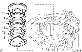
Install the brake piston return spring.
Install the 3 plates, 3 discs and flange.
- Install in order:
*1 - *2 - *1 - *2 - *1 - *2 - *3
| *1 | Disc |
| *2 | Plate |
| *2 | Flange |
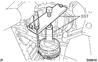
Using SST and a press, compress the return spring and install the No. 2 brake spring snap ring.
- SST
- 09351-40010
35621V
16.INSTALL NO. 1 BRAKE PISTON
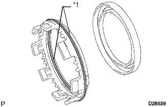
Coat 2 new O-rings with ATF and install them to the brake piston.
| *1 | New O-Ring |
Press the brake piston into the brake cylinder with both hands.
- NOTICE:
-
Be careful not to damage the O-rings.
35608J
17.INSTALL BRAKE PISTON RETURN SPRING SUB-ASSEMBLY
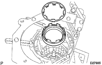
Install the No. 1 brake piston with No. 1 brake cylinder and the brake piston return spring to the transmission case.
35608K
18.INSTALL BRAKE PISTON RETURN SPRING SNAP RING
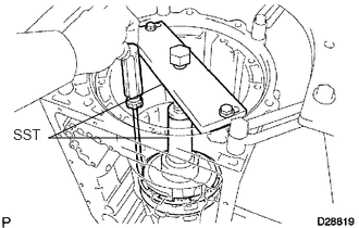
Using SST and a press, compress the return spring and install the brake piston return spring snap ring.
- SST
- 09351-40010
35676B
19.SELECT NO. 1 BRAKE FLANGE
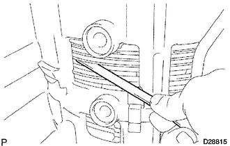
Using a feeler gauge, measure the distance between the snap ring and flange.
- HINT:
-
0.42 to 0.72 mm (0.0165 to 0.0283 in.)
If the distance is outside the specification, parts may have been assembled incorrectly. Perform the reassembly again. If the distance is still outside the specification, select No. 1 brake flange so that the value of measured distance is 0.42 to 0.72 mm (0.0165 to 0.0283 in.).
- Flange Thickness:
Mark Thickness 0 1.95 to 2.05 mm (0.0768 to 0.0807 in.) 1 2.15 to 2.25 mm (0.0846 to 0.0886 in.) 2 2.35 to 2.45 mm (0.0925 to 0.0965 in.) 3 2.55 to 2.65 mm (0.100 to 0.104 in.)
35681A
20.INSTALL NO. 1 BRAKE DISC
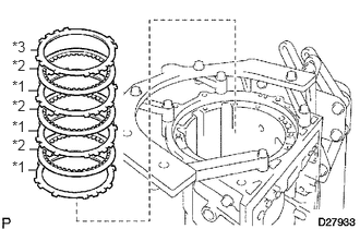
Install the 3 plates, 3 discs and flange.
- Install in order:
*1 - *2 - *1 - *2 - *1 - *2 - *3
| *1 | Plate |
| *2 | Disc |
| *3 | Flange |
35763
21.INSTALL CENTER PLANETARY RING GEAR
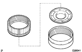
Install the center planetary ring gear and front planetary ring gear flange to the front planetary ring gear.
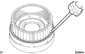
Using a screwdriver, install the snap ring.
35743
22.INSTALL FRONT PLANETARY RING GEAR
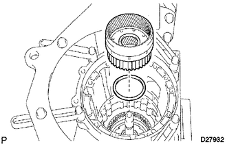
Install the thrust needle roller bearing and front planetary ring gear to the case.
- Thrust Needle Roller Bearing Diameter:
Item Inside Outside Bearing G 55.8 to 56.0 mm (2.197 to 2.204 in.) 76.1 to 76.4 mm (2.996 to 3.008 in.)
35720
23.INSTALL FRONT PLANETARY GEAR ASSEMBLY
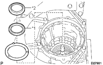
Install the thrust washer and thrust needle roller bearing.
Coat the No. 5 thrust race with petroleum jelly and install it to the front planetary ring gear.
- Thrust Needle Roller Bearing and Race Diameter:
Item Inside Outside Bearing F 43.4 to 43.6 mm (1.71 to 1.72 in.) 58.0 to 58.4 mm (2.28 to 2.30 in.) Race F 38.0 to 38.2 mm (1.496 to 1.504 in.) 56.5 to 57.0 mm (2.22 to 2.24 in.)
| *1 | Bearing F |
| *2 | Race F |
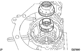
Install the front planetary gear assembly and 1-way clutch inner race to the case.
35624
24.INSTALL 2ND BRAKE PISTON
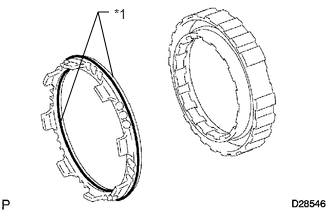
Coat 2 new O-rings with ATF and install them to the 2nd brake piston.
| *1 | New O-Ring |
Press the 2nd brake cylinder into the 2nd brake piston with both hands.
- NOTICE:
-
Be careful not to damage the O-rings.
Install the return spring to the 2nd brake cylinder.
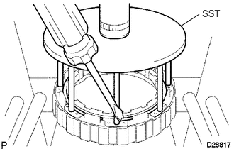
Using SST and a press, compress the return spring and install the snap ring.
- SST
- 09351-40010
- NOTICE:
-
Make sure the end gap of the snap ring is not aligned with the spring retainer claw.
35664
25.INSTALL 2ND BRAKE CYLINDER
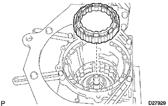
Install the 2nd brake cylinder to the case.
35790
26.INSTALL 1-WAY CLUTCH ASSEMBLY
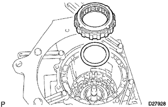
Install the thrust washer and 1-way clutch to the case.
35624J
27.INSTALL 2ND BRAKE PISTON HOLE SNAP RING
Using SST, install the snap ring.
- SST
- 09350-30020 (09350-07060)
28.INSTALL NO. 3 BRAKE DISC
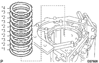
Install the cushion plate, 4 plates, 4 discs and flange to the case.
- Install in order:
*1 - *2 - *3 - *2 - *3 - *2 - *3 - *2 - *3 - *4
| *1 | Cushion Plate |
| *2 | Plate |
| *3 | Disc |
| *4 | Flange |
35679C
29.INSTALL NO. 3 BRAKE SNAP RING
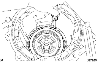
Using a screwdriver, install the snap ring.
35606A
30.INSTALL DIRECT CLUTCH PISTON SUB-ASSEMBLY
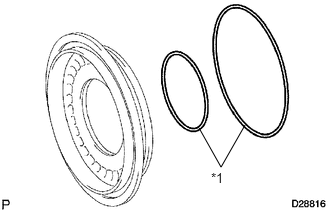
Coat 2 new O-rings with ATF and install them to the direct clutch piston.
| *1 | New O-Ring |
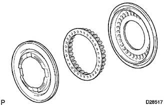
Install the direct clutch return spring and No. 2 clutch balancer to the direct clutch piston.
Press the direct clutch piston into the clutch drum with both hands.
- NOTICE:
-
Be careful not to damage the O-rings.
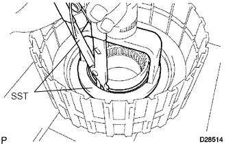
Place SST on the direct clutch piston and compress the return spring with a press.
- NOTICE:
-
Stop pressing when the spring sheet is lowered to a position 1 to 2 mm (0.039 to 0.078 in.) from the snap ring groove to prevent the spring sheet from being deformed.
- SST
- 09320-89010
09350-30020 (09350-07070)
Install the snap ring with a snap ring expander.
- NOTICE:
-
Do not expand the snap ring excessively.
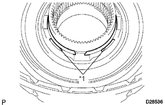
Position the end gap of the snap ring as shown in the illustration
| *1 | Stopper |
- NOTICE:
-
Make sure the end gap of the snap ring is not aligned with the spring retainer claw.
35048
31.INSTALL REVERSE CLUTCH PISTON SUB-ASSEMBLY
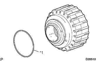
Coat a new O-ring with ATF and install it to the clutch drum.
| *1 | New O-Ring |
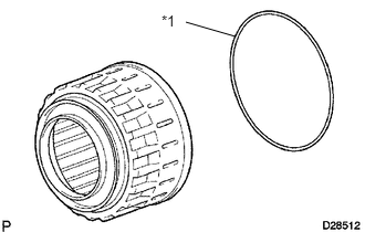
Coat a new O-ring with ATF and install it to the reverse clutch piston.
| *1 | New O-Ring |
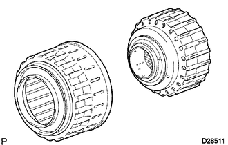
Press the clutch drum into the reverse clutch piston with both hands.
- NOTICE:
-
Be careful not to damage the O-ring.
35047
32.INSTALL REVERSE CLUTCH RETURN SPRING SUB-ASSEMBLY
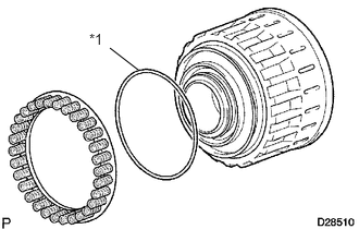
Coat a new O-ring with ATF and install it to the reverse clutch piston.
| *1 | New O-Ring |
Install the reverse clutch return spring to the reverse clutch piston.
35688
33.INSTALL NO. 3 CLUTCH BALANCER
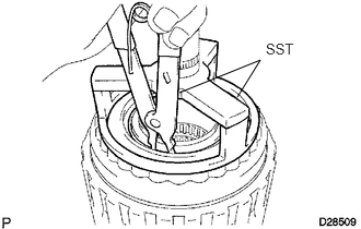
Place SST on the No. 3 clutch balancer and compress the clutch balancer with a press.
- SST
- 09387-00070
09350-30020 (09350-07070)
- NOTICE:
-
Stop pressing when the spring sheet is lowered to a position 1 to 2 mm (0.0393 to 0.0787 in.) from the snap ring groove to prevent the spring sheet from being deformed.
Install the snap ring with a snap ring expander.
- NOTICE:
-
Do not expand the snap ring excessively.
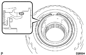
Position the end gap of the snap ring as shown in the illustration.
- NOTICE:
-
Make sure the end gap of the snap ring is not aligned with the spring retainer claw.
35667A
34.INSTALL DIRECT CLUTCH DISC
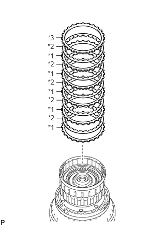
Install the 5 plates, 5 discs and reverse clutch flange to the clutch drum.
- Install in order:
*1 - *2 - *1 - *2 - *1 - *2 - *1 - *2 - *1 - *2 - *3
| *1 | Plate |
| *2 | Disc |
| *3 | Flange |
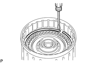
Using a screwdriver, install the snap ring to the clutch drum.
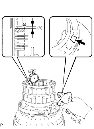
Using a dial indicator, measure the moving distance (A) of the clutch flange at both ends across the diameter while applying compressed air into the oil hole as shown in the illustration.
- Standard moving distance (A):
0.55 to 0.85 mm (0.0217 to 0.0335 in.)
- NOTICE:
-
When measuring the moving distance, install a standard flange (thickness: 3.4 mm (0.134 in.)) to the position indicated by the shaded area in the illustration.
If the moving distance (A) is not as specified, select a flange of an appropriate thickness from the table below so that the measured value is within the standard range.
- Flange Thickness:
Mark Thickness 2 2.95 to 3.05 mm (0.116 to 0.120 in.) 3 3.05 to 3.15 mm (0.120 to 0.124 in.) 4 3.15 to 3.25 mm (0.124 to 0.128 in.) 5 3.25 to 3.35 mm (0.128 to 0.132 in.) 6 3.35 to 3.45 mm (0.132 to 0.136 in.) 7 3.45 to 3.55 mm (0.136 to 0.140 in.) 8 3.55 to 3.65 mm (0.140 to 0.144 in.) 9 3.65 to 3.75 mm (0.144 to 0.148 in.) A 3.75 to 3.85 mm (0.148 to 0.152 in.)
Temporarily remove the snap ring, replace the flange with the selected flange and reinstall the snap ring.
35649
35.SELECT REVERSE CLUTCH FLANGE
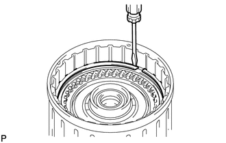
Using a screwdriver, install the snap ring to the clutch drum.
- NOTICE:
-
Make sure to install the direct clutch and reverse clutch snap rings so that their openings face opposite directions.
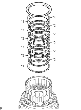
Install the 2 flanges, 5 discs, 4 plates, cushion plate and reverse clutch reaction sleeve to the clutch drum.
- Install in order:
*1 - *2 - *3 - *2 - *3 - *2 - *3 - *2 - *3 - *2 - *1 - *4
| *1 | Flange |
| *2 | Disc |
| *3 | Plate |
| *4 | Cushion Plate |
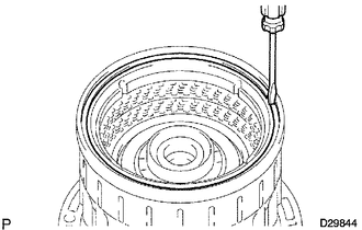
Using a screwdriver, install the hole snap ring.
Using a dial indicator, measure the moving distance (A minus B) of the top surface of the reverse clutch piston (A) and cushion plate at both ends across the diameter (B) while applying compressed air (392 kPa, 4.0 kgf/ cm2, 57 psi) into the oil hole as shown in the illustration. Then choose a flange of an appropriate thickness from the table so that the measured value is within the standard range.
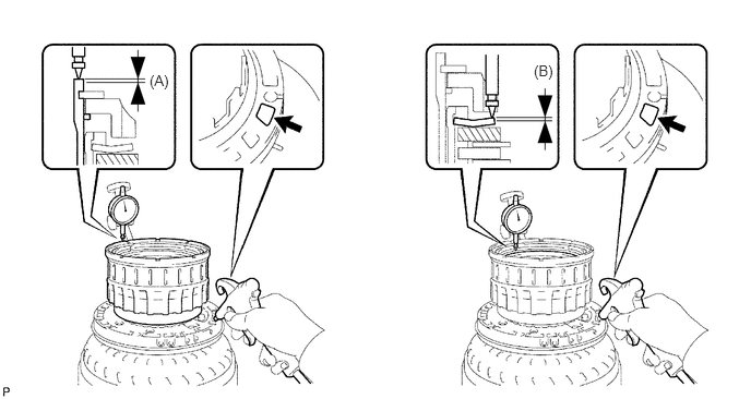
- Standard moving distance (A minus B):
0.56 to 0.86 mm (0.0220 to 0.0339 in.)
- NOTICE:
-
When measuring the moving distance, install a standard flange (thickness: 3.3 mm (0.130 in.)) to the position indicated by the shaded area in the illustration.
- HINT:
-
Distance (A) = 1.05 to 2.15 mm (0.0413 to 0.0846 in.)
-
Distance (B) = 0.72 to 1.08 mm (0.0283 to 0.0425 in.)
- Flange Thickness:
Mark Thickness 0 2.75 to 2.85 mm (0.108 to 0.112 in.) 1 2.85 to 2.95 mm (0.112 to 0.116 in.) 2 2.95 to 3.05 mm (0.116 to 0.120 in.) 3 3.05 to 3.15 mm (0.120 to 0.124 in.) 4 3.15 to 3.25 mm (0.124 to 0.128 in.) 5 3.25 to 3.35 mm (0.128 to 0.132 in.) 6 3.35 to 3.45 mm (0.132 to 0.136 in.) 7 3.45 to 3.55 mm (0.136 to 0.140 in.) 8 3.55 to 3.65 mm (0.140 to 0.144 in.) 9 3.65 to 3.75 mm (0.144 to 0.148 in.) A 3.75 to 3.85 mm (0.148 to 0.152 in.)
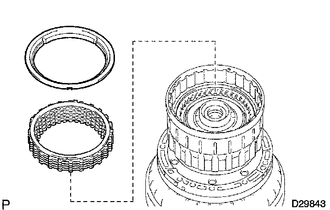
Remove the snap ring, reverse clutch reaction sleeve and rear clutch disc set from the clutch drum.
35659
36.REMOVE REVERSE CLUTCH REACTION SLEEVE
Using a screwdriver, remove the snap ring from the clutch drum.
Remove the reverse clutch reaction sleeve, clutch cushion plate, reverse clutch flange, 5 reverse clutch discs and 4 clutch plates from the reverse clutch hub.
35712A
37.INSTALL INPUT SHAFT OIL SEAL RING
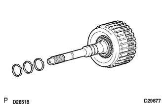
Coat 3 new oil seal rings with ATF.
Squeeze the ends of the 3 oil seal rings together, and then install them to the starter shaft groove.
- NOTICE:
-
Do not excessively widen the rings.
- HINT:
-
After installing the oil seal rings, check that they rotate smoothly.
35612B
38.INSTALL FORWARD CLUTCH PISTON
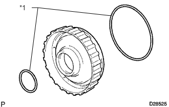
Coat 2 new O-rings with ATF and install them to the forward clutch piston.
| *1 | New O-Ring |
Install the forward clutch piston to the input shaft.
35668
39.INSTALL NO. 1 CLUTCH BALANCER
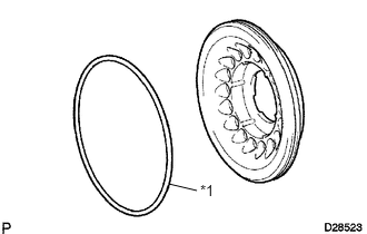
Coat a new O-ring with ATF and install it to the clutch balancer.
| *1 | New O-Ring |
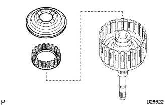
Install the forward clutch return spring and clutch balancer.
- NOTICE:
-
Be careful not to damage the O-ring.
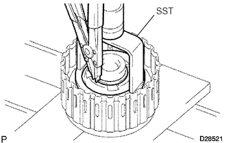
Place SST on the No. 1 clutch balancer and compress the return spring with a press.
- SST
- 09350-30020 (09350-07040, 09350-07070)
- NOTICE:
-
Stop pressing when the spring sheet is lowered to a position 1 to 2 mm (0.0393 to 0.0787 in.) from the snap ring groove to prevent the spring sheet from being deformed.
Install the snap ring with a snap ring expander.
- NOTICE:
-
Do not expand the snap ring excessively.
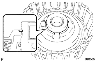
Position the end gap of the snap ring as shown in the illustration.
- NOTICE:
-
Make sure the end gap of the snap ring is not aligned with the spring retainer claw.
35633B
40.INSTALL FORWARD MULTIPLE DISC CLUTCH DISC
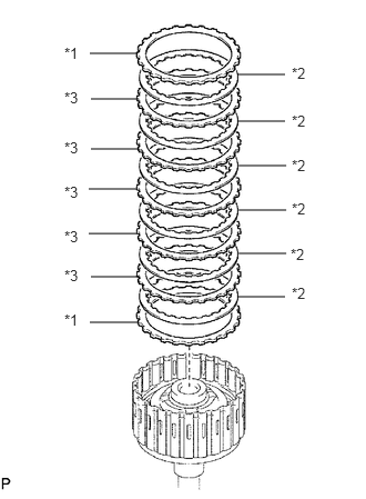
Install the 2 flanges, 6 discs and 5 plates to the input shaft assembly.
- Install in order:
*1 - *2 - *3 - *2 - *3 - *2 - *3 - *2 - *3 - *2 - *3 - *2 - *1
| *1 | Flange |
| *2 | Disc |
| *3 | Plate |
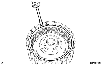
Using a screwdriver, temporarily install the snap ring.
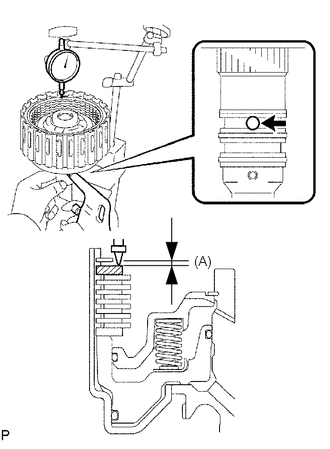
Using a dial indicator, measure the moving distance (A) of the clutch flange at both ends across the diameter while applying compressed air into the oil hole as shown in the illustration.
- Standard moving distance (A):
0.61 to 0.91 mm (0.0240 to 0.0358 in.)
- NOTICE:
-
When measuring the moving distance, install a standard flange (thickness: 3.4 mm (0.134 in.)) to the position indicated by the shaded area in the illustration.
- HINT:
-
Moving distance (A): 0.26 to 1.36 mm (0.0102 to 0.0535 in.)
If the moving distance (A) is not as specified, select a flange of an appropriate thickness from the table below so that the measured value is within the standard range.
- Flange Thickness:
Mark Thickness 0 2.95 to 3.05 mm (0.116 to 0.120 in.) 1 3.05 to 3.15 mm (0.120 to 0.124 in.) 2 3.15 to 3.25 mm (0.124 to 0.128 in.) 3 3.25 to 3.35 mm (0.128 to 0.132 in.) 4 3.35 to 3.45 mm (0.132 to 0.136 in.) 5 3.45 to 3.55 mm (0.136 to 0.140 in.) 6 3.55 to 3.65 mm (0.140 to 0.144 in.) 7 3.65 to 3.75 mm (0.144 to 0.148 in.) 8 3.75 to 3.85 mm (0.148 to 0.152 in.) 9 3.85 to 3.95 mm (0.148 to 0.152 in.) A 3.95 to 4.05 mm (0.152 to 0.159 in.)
Temporarily remove the snap ring, replace the flange with the selected flange and reinstall the snap ring.
35701
41.INSTALL INPUT SHAFT ASSEMBLY
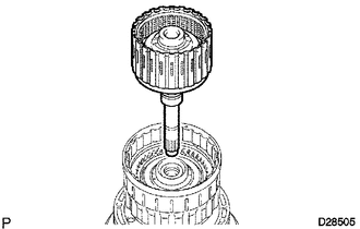
Install the input shaft to the clutch drum.
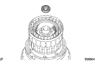
Install the thrust needle roller bearing to the clutch drum.
- Thrust Needle Roller Bearing Diameter:
Item Inside Outside Bearing C 21.4 to 21.6 mm (0.841 to 0.850 in.) 40.8 to 41.0 mm (1.606 to 1.614 in.)
35631
42.INSTALL MULTIPLE DISC CLUTCH HUB
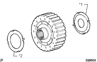
Coat the 2 thrust bearing races with petroleum jelly and install them to the multiple disc clutch hub.
- Thrust Bearing Race Diameter:
Item Inside Outside Race C 22.7 to 22.9 mm (0.892 to 0.902 in.) 60.0 to 60.4 mm (2.36 to 2.38 in.) Race D 33.3 to 33.5 mm (1.31 to 1.32 in.) 56.3 to 56.6 mm (2.22 to 2.23 in.)
| *1 | Race C |
| *2 | Race D |
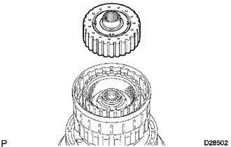
Install the multiple disc clutch hub to the clutch drum.
35061
43.INSTALL FORWARD CLUTCH HUB SUB-ASSEMBLY
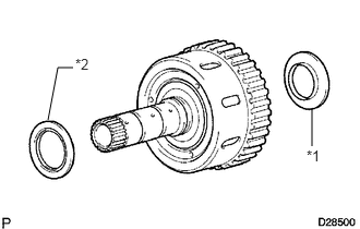
Coat the 2 thrust needle roller bearings with petroleum jelly and install them to the forward clutch hub.
- Thrust Needle Roller Bearing Diameter:
Item Inside Outside Bearing D 38.5 to 38.7 mm (1.515 to 1.524 in.) 56.5 to 57.0 mm (2.22 to 2.24 in.) Bearing E 42.6 to 42.8 mm (1.68 to 1.69 in.) 60.8 to 61.1 mm (2.39 to 2.41 in.)
| *1 | Bearing D |
| *2 | Bearing E |
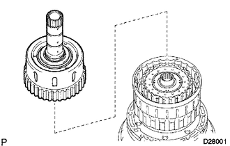
Install the forward clutch hub to the clutch drum.
35677C
44.INSTALL REAR CLUTCH DISC
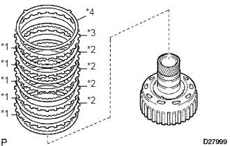
Install the 5 discs, 4 plates, reverse clutch flange and clutch cushion plate to the reverse clutch hub.
- Install in order:
*1 - *2 - *1 - *2 - *1 - *2 - *1 - *2 - *1 - *3 - *4
| *1 | Disc |
| *2 | Plate |
| *3 | Flange |
| *4 | Cushion Plate |
35659
45.INSTALL REVERSE CLUTCH REACTION SLEEVE
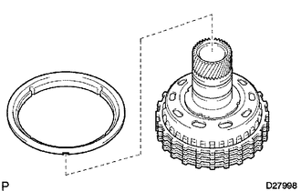
Install the reverse clutch reaction sleeve to the reverse clutch hub.
35049
46.INSTALL REVERSE CLUTCH HUB SUB-ASSEMBLY
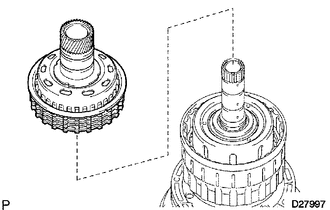
Install the reverse clutch hub to the clutch drum.
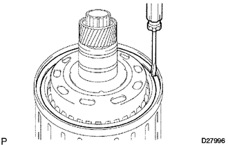
Using a screwdriver, install the snap ring to the clutch drum and input shaft.
35780B
47.INSTALL NO. 2 1-WAY CLUTCH ASSEMBLY
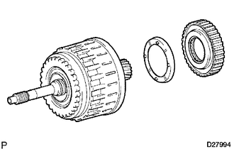
Coat the No. 2 clutch drum thrust washer with petroleum jelly and install it to the clutch drum.
Install the 1-way clutch to the clutch drum.
48.INSTALL CLUTCH DRUM AND INPUT SHAFT ASSEMBLY
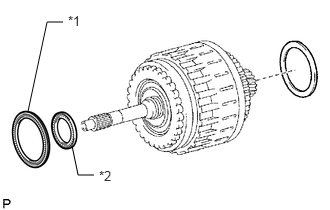
Coat the 2 thrust needle roller bearings and clutch drum thrust washer with petroleum jelly and install them to the clutch drum and input shaft assembly.
- Thrust Needle Roller Bearing Diameter:
Item Inside Outside Bearing A 72.0 to 72.3 mm (2.83 to 2.85 in.) 85.3 to 85.6 mm (3.36 to 3.37 in.) Bearing B 34.7 to 34.9 mm (1366 to 1.374 in.) 51.6 to 51.9 mm (2.03 to 2.04 in.)
| *1 | Bearing A |
| *2 | Bearing B |
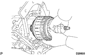
Install the clutch drum and input shaft assembly to the transmission case.
49.INSTALL OIL PUMP ASSEMBLY
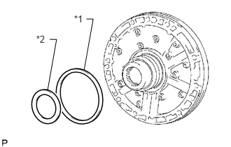
Coat the No. 1 and No. 2 thrust bearing races with petroleum jelly and install them to the front oil pump.
- Thrust Bearing Race Diameter:
Item Inside Outside Race A 74.3 to 74.6 mm (2.93 to 2.94 in.) 87.4 to 87.7 mm (3.44 to 3.45 in.) Race B 37.0 to 37.3 mm (1.46 to 1.47 in.) 52.1 to 52.3 mm (2.05 to 2.06 in.)
| *1 | Race A |
| *2 | Race B |
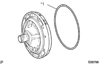
Coat a new O-ring with ATF and install it to the oil pump assembly.
| *1 | New O-Ring |
Slide the oil pump onto the input shaft, align the bolt holes of the oil pump assembly with the bolt holes of the transmission case and install the oil pump.
Hold the input shaft, and lightly press the oil pump body to slide the oil seal rings into the overdrive direct clutch drum.
- NOTICE:
-
Do not excessively push on the oil pump, as the oil seal rings will stick to the direct clutch drum.
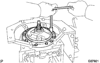
Install the 10 bolts.
- Torque:
- 21 N*m (215 kgf*cm, 16 ft.*lbf)
35506F
50.INSTALL MANUAL VALVE LEVER SHAFT OIL SEAL
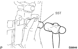
Using SST and a hammer, tap in 2 new oil seals.
- SST
- 09350-30020 (09350-07110)
Coat the lips of the oil seals with MP grease.
51.INSPECT INDIVIDUAL PISTON OPERATION
35505
52.INSTALL MANUAL VALVE LEVER SUB-ASSEMBLY
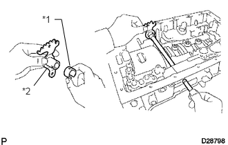
Install a new spacer to the manual valve lever.
| *1 | Spacer |
| *2 | Manual Valve Lever |
Push the manual valve lever shaft through the transmission case, and install the manual valve lever to the manual valve lever shaft.
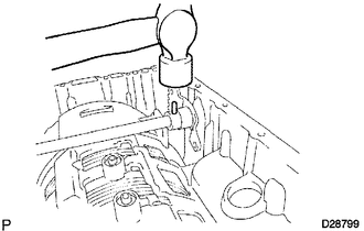
Using a hammer, tap in a new spring pin.
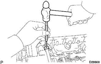
Align the manual valve lever indentation with the spacer hole, and stake them together with a punch.
Check that the shaft rotates smoothly.
35556
53.INSTALL PARKING LOCK PAWL SHAFT
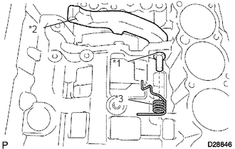
Install the E-ring to the shaft.
Install the parking lock pawl, shaft and spring.
| *1 | E-Ring |
| *2 | Parking Lock Pawl |
| *3 | Spring |
35501
54.INSTALL PARKING LOCK ROD SUB-ASSEMBLY
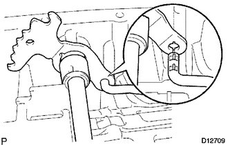
Connect the parking lock rod to the manual valve lever to install it.
35595
55.INSTALL PARKING LOCK PAWL BRACKET
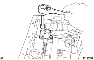
Install the parking lock pawl bracket to the transmission case with the 3 bolts.
- Torque:
- 7.4 N*m (75 kgf*cm, 65 in.*lbf)
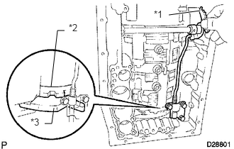
Move the manual valve lever to the P position, and confirm that the planetary ring gear is correctly locked by the lock pawl.
| *1 | Manual Valve Lever |
| *2 | Planetary Ring Gear |
| *3 | Parking Lock Pawl |
35424F
56.INSTALL C-1 ACCUMULATOR VALVE
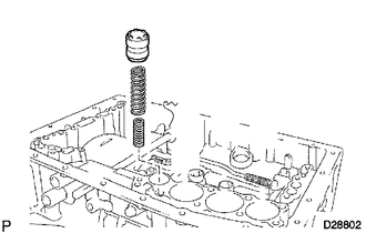
Install the 2 springs and accumulator valve to the hole.
- Accumulator Spring Diameter:
Spring Free Length
Outer DiameterColor C-1 Inner 30.40 mm (1.20 in.)
11.40 mm (0.449 in.)Pink C-1 Outer 48.76 mm (1.92 in.)
16.60 mm (0.654 in.)Light Green
35426D
57.INSTALL C-3 ACCUMULATOR PISTON
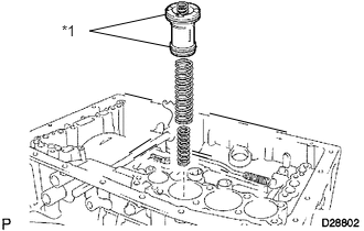
Coat 2 new O-rings with ATF and install them to the piston.
| *1 | New O-Ring |
Install the 2 springs and accumulator piston to the hole.
- Accumulator Spring Diameter:
Spring Free Length
Outer DiameterColor C-3 Inner 44.0 mm (1.73 in.)
14.0 mm (0.551 in.)Yellow C-3 Outer 73.35 mm (2.89 in.)
19.90 mm (0.784 in.)Red
35427K
58.INSTALL B-3 ACCUMULATOR PISTON
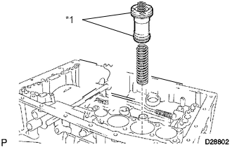
Coat 2 new O-rings with ATF and install them to the piston.
| *1 | New O-Ring |
Install the spring and accumulator piston to the hole.
- Accumulator Spring Diameter:
Spring Free Length
Outer DiameterColor B-3 70.5 mm (2.78 in.)
19.7 mm (0.776 in.)Purple
35425A
59.INSTALL C-2 ACCUMULATOR PISTON
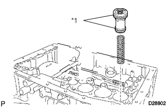
Coat 2 new O-rings with ATF and install them to the piston.
| *1 | New O-Ring |
Install the spring and accumulator piston to the hole.
- Accumulator Spring Diameter:
Spring Free Length
Outer DiameterColor C-2 62.0 mm (2.44 in.)
15.9 mm (0.626 in.)White
35159
60.INSTALL BRAKE DRUM GASKET
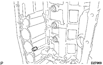
Install the 3 brake drum gaskets.
35145C
61.INSTALL TRANSMISSION CASE GASKET
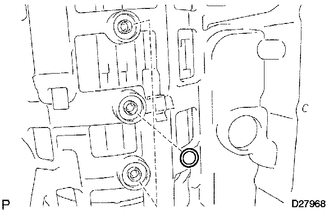
Install the 3 transmission case gaskets.
35251
62.INSTALL CHECK BALL BODY
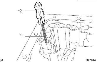
Install the spring and check ball body.
| *1 | Spring |
| *2 | Check Ball Body |
35410
63.INSTALL TRANSMISSION VALVE BODY ASSEMBLY
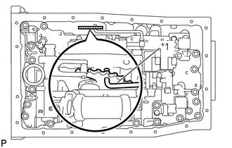
Insert the pin of the manual valve into the hole of the manual valve lever.
| *1 | Pin |
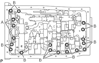
Install the transmission valve body assembly with the 19 bolts.
- Torque:
- 11 N*m (112 kgf*cm, 8 ft.*lbf)
- HINT:
-
Each bolt length is indicated below.
-
36 mm (1.42 in.) for bolt A
-
25 mm (0.984 in.) for bolt B
Install the detent spring and detent spring cover with the bolt.
- Torque:
- 10 N*m (102 kgf*cm, 7 ft.*lbf)
82125J
64.INSTALL TRANSMISSION WIRE
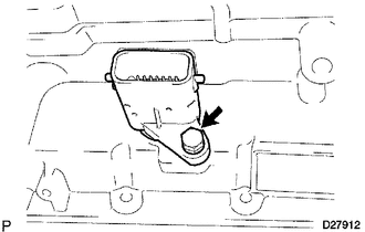
Coat a new O-ring with ATF and install it to the transmission wire connector.
Install the transmission wire harness.
Install the bolt.
- Torque:
- 5.4 N*m (55 kgf*cm, 48 in.*lbf)
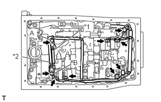
Connect the 7 solenoid connectors.
Connect the 2 ATF temperature sensors with the 2 clamps and 2 bolts.
- Torque:
- for bolt A : 10 N*m (102 kgf*cm, 7 ft.*lbf)
- for bolt B : 11 N*m (112 kgf*cm, 8 ft.*lbf)
| *1 | No. 1 Temperature Sensor |
| *2 | No. 2 Temperature Sensor |
- HINT:
-
Each bolt length is indicated below.
-
12 mm (0.472 in.) for bolt A
-
36 mm (1.42 in.) for bolt B
| Wire Harness | Color |
|---|---|
| No. 1 temperature sensor | Orange |
| No. 2 temperature sensor | Blue |
35330
65.INSTALL VALVE BODY OIL STRAINER ASSEMBLY
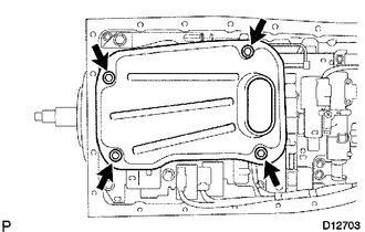
Coat a new O-ring with ATF and install it to the valve body oil strainer assembly.
Install the oil strainer with the 4 bolts.
- Torque:
- 10 N*m (102 kgf*cm, 7 ft.*lbf)
35394
66.INSTALL TRANSMISSION OIL CLEANER MAGNET
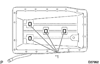
Install the 4 magnets.
| *1 | Magnet |
35106
67.INSTALL AUTOMATIC TRANSMISSION OIL PAN SUB-ASSEMBLY
Install a new gasket to the oil pan.
Install the oil pan with the 20 bolts.
- Torque:
- 7.0 N*m (71 kgf*cm, 62 in.*lbf)
Install the drain plug.
- Torque:
- 20 N*m (204 kgf*cm, 15 ft.*lbf)
35108R
68.INSTALL AUTOMATIC TRANSMISSION EXTENSION HOUSING OIL SEAL
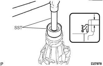
Coat the lip of a new oil seal with ATF.
Using SST and a hammer, tap in the oil seal.
- SST
- 09710-30050
09950-70010 (09951-07100)
- Standard depth:
5.4 to 5.8 mm (0.213 to 0.228 in.)
69.INSTALL EXTENSION HOUSING DUST DEFLECTOR
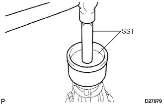
Using SST and a hammer, tap in a new dust deflector.
- SST
- 09223-15020
09950-70010 (09951-07100)
35108
70.INSTALL EXTENSION HOUSING SUB-ASSEMBLY
Clean the threads of the bolts and case with non residue solvent.
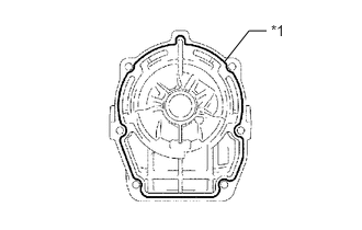
Apply seal packing to the extension housing.
- Seal packing:
Toyota Genuine Seal Packing 1281,
Three Bond 1281 or equivalent
- Seal diameter:
1.0 to 1.5 mm (0.0394 to 0.0591 in.)
| *1 | Seal Packing |
Apply adhesive to the threads of the 6 bolts.
- Adhesive:
Toyota Genuine Adhesive 1324,
Three Bond 1324 or equivalent
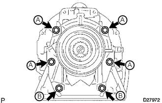
Install the extension housing with the 6 bolts.
- Torque:
- 34 N*m (345 kgf*cm, 25 ft.*lbf)
- HINT:
-
Each bolt length is indicated below.
-
45 mm (1.77 in.) for bolt A
-
35 mm (1.38 in.) for bolt B
35111
71.INSTALL AUTOMATIC TRANSMISSION HOUSING
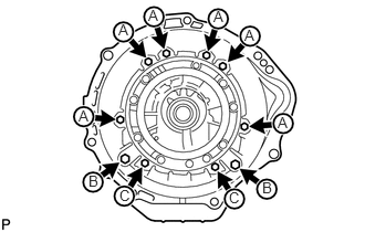
Clean the threads of the bolts and case with non-residue solvent.
Install the transmission housing with the 10 bolts.
- Torque:
- for 14 mm head bolt A : 34 N*m (345 kgf*cm, 25 ft.*lbf)
- for 17 mm head bolt B : 57 N*m (579 kgf*cm, 42 ft.*lbf)
- for 14 mm head bolt C : 34 N*m (345 kgf*cm, 25 ft.*lbf)
35122
72.INSTALL AUTOMATIC TRANSMISSION BREATHER TUBE
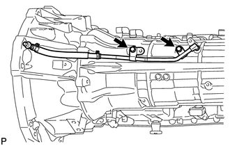
Coat a new O-ring with ATF and install it to the breather tube.
Install the breather tube with the 2 bolts.
- Torque:
- 5.4 N*m (55 kgf*cm, 48 in.*lbf)
89413B
73.INSTALL SPEED SENSOR
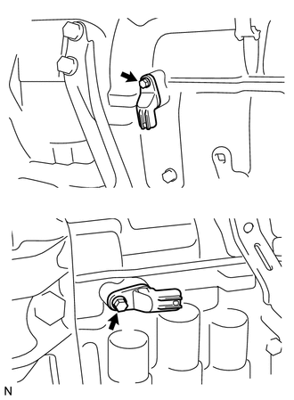
Coat 2 new O-rings with ATF and install one to each speed sensor.
Install the 2 speed sensors.
Install the 2 bolts.
- Torque:
- 5.4 N*m (55 kgf*cm, 48 in.*lbf)
32921C
74.INSTALL OIL COOLER TUBE UNION
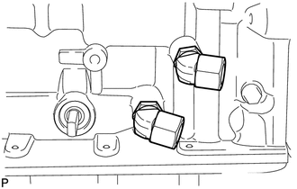
Coat a new O-ring with ATF and install one to each oil cooler tube union.
Install the oil cooler tube union.
- Torque:
- 29 N*m (300 kgf*cm, 22 ft.*lbf)
84540
75.INSTALL PARK/NEUTRAL POSITION SWITCH ASSEMBLY
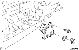
Install the park/neutral position switch to the manual valve lever shaft, and temporarily install the adjusting bolt.
Install a new lock washer and the nut.
- Torque:
- 6.9 N*m (70 kgf*cm, 61 in.*lbf)
Temporarily install the control shaft lever.
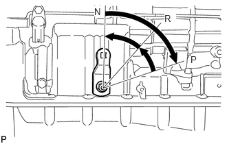
Turn the control shaft lever clockwise until it stops, and then turn it counterclockwise 2 notches to set it to the N position.
Remove the control shaft lever.
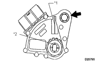
Align the neutral basic line with the switch groove, and tighten the adjusting bolt.
| *1 | Neutral Basic Line |
| *2 | Groove |
- Torque:
- 13 N*m (130 kgf*cm, 9 ft.*lbf)
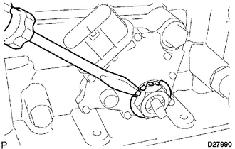
Using a screwdriver, bend the tabs of the lock washer.
- HINT:
-
Bend at least 2 of the lock washer tabs.
35573
76.INSTALL TRANSMISSION CONTROL SHAFT LEVER LH
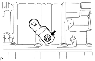
Install the control shaft lever with the spring washer and nut.
- Torque:
- 16 N*m (160 kgf*cm, 12 ft.*lbf)