Home › Audio / Visual / Telematics › AUDIO / VIDEO › AUDIO AND VISUAL SYSTEM › 2009.08–2013.08
RM1440E _56 Audio / Visual / Telematics _056150 AUDIO / VIDEO _0274026 AUDIO AND VISUAL SYSTEM J

AUDIO / VIDEO  AUDIO AND VISUAL SYSTEM  AVC-LAN Circuit  


DESCRIPTION

Each unit of the audio system connected to the AVC-LAN (communication bus) transfers the signal of each switch by communication.

When a short to +B or short to ground occurs in this AVC-LAN, the audio system will not function normally as the communication is discontinued.

WIRING DIAGRAM
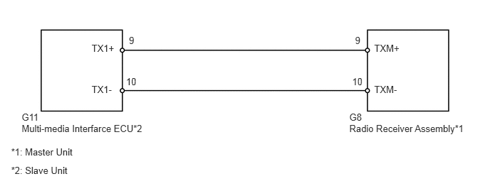
E204412E01
0.317,1.636 0.656,1.803 0.339,0.167 10 G11 0.317,1.804 2.212,1.971 1.895,0.167 10 Multi-media Interfarce ECU*2 0.163,2.141 1.912,2.307 1.749,0.167 10 *1: Master Unit 0.163,2.421 1.912,2.588 1.749,0.167 10 *2: Slave Unit 5.109,1.636 5.448,1.803 0.339,0.167 10 G8 5.473,1.23 5.916,1.397 0.444,0.167 10 TXM- 5.473,0.628 5.916,0.794 0.444,0.167 10 TXM+ 5.151,1.118 5.358,1.285 0.207,0.167 10 10 5.193,0.515 5.345,0.682 0.152,0.167 10 9 1.34,1.23 1.728,1.397 0.388,0.167 10 TX1- 1.34,0.628 1.728,0.794 0.388,0.167 10 TX1+ 1.844,1.118 2.052,1.285 0.207,0.167 10 10 1.886,0.515 2.038,0.682 0.152,0.167 10 9 5.109,1.804 6.920,1.971 1.812,0.167 10 Radio Receiver Assembly*1

PROCEDURE

1.INSPECT RADIO RECEIVER ASSEMBLY
a.
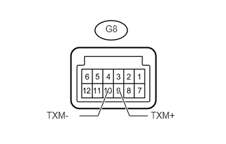
U181066E03
1.646,1.365 1.49,1.76 1.49,1.76 1.208,1.76 true 1.813,1.365 1.969,1.76 1.969,1.76 2.25,1.76 true 0.708,1.667 1.104,1.885 0.396,0.219 10 false TXM- 1.604,0.354 1.906,0.573 0.302,0.219 10 false G8 2.292,1.667 2.771,1.885 0.479,0.219 10 false TXM+

Disconnect the G8 radio receiver assembly connector.


b.

Measure the resistance according to the value(s) in the table below.

Standard Resistance:
Tester Connection Condition Specified Condition
G8-9 (TXM+) - G8-10 (TXM-) Always 60 to 80 Ω


OK

2.CHECK HARNESS AND CONNECTOR (RADIO RECEIVER - COMPONENT WHICH HAS STORED THIS CODE)

NG

REPLACE RADIO RECEIVER ASSEMBLY

2.CHECK HARNESS AND CONNECTOR (RADIO RECEIVER - COMPONENT WHICH HAS STORED THIS CODE)
HINT:

For details of the connectors, refer to Terminals of ECU (See page Audio / Visual / Telematics>AUDIO / VIDEO>AUDIO AND VISUAL SYSTEM>TERMINALS OF ECU).


a.

Referring to the wiring diagram, check the AVC-LAN circuit between the radio receiver assembly and the component which has stored this code.

i.

Disconnect all connectors between the radio receiver assembly and the component which has stored this code.


ii.

Check for an open or short in the AVC-LAN circuit between the radio receiver assembly and the component which has stored this code.

OK:

There is no open or short circuit.


OK

PROCEED TO NEXT SUSPECTED AREA SHOWN IN PROBLEM SYMPTOMS TABLE

NG

REPAIR OR REPLACE HARNESS OR CONNECTOR