Home › Audio / Visual / Telematics › AUDIO / VIDEO › AUDIO AND VISUAL SYSTEM › 2009.08–2013.08
RM1440E _56 Audio / Visual / Telematics _056150 AUDIO / VIDEO _0274026 AUDIO AND VISUAL SYSTEM J

AUDIO / VIDEO  AUDIO AND VISUAL SYSTEM  Speaker Circuit  


DESCRIPTION

The radio receiver assembly sends sound signals to the speaker.

WIRING DIAGRAM
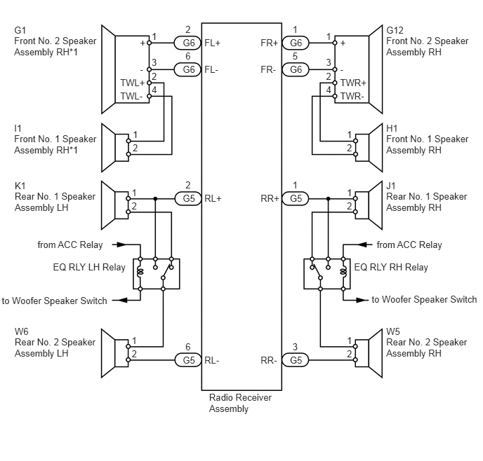
E204415E01
4.301,0.552 4.515,0.707 0.215,0.155 10 G6 5.731,0.36 7.010,0.573 1.279,0.214 10 G12 5.731,0.518 7.010,0.840 1.279,0.321 10 Front No. 2 Speaker Assembly RH 5.731,1.82 7.010,2.033 1.279,0.214 10 H1 5.731,1.978 7.010,2.300 1.279,0.321 10 Front No. 1 Speaker Assembly RH 4.341,0.353 4.555,0.508 0.215,0.155 10 1 4.301,0.949 4.515,1.104 0.215,0.155 10 G6 5.047,0.552 5.487,0.707 0.440,0.155 10 + 5.047,0.949 5.487,1.104 0.440,0.155 10 - 5.047,1.148 5.487,1.303 0.440,0.155 10 TWR+ 5.047,1.346 5.487,1.501 0.440,0.155 10 TWR- 3.867,0.552 4.173,0.707 0.306,0.155 10 FR+ 3.867,0.949 4.173,1.104 0.306,0.155 10 FR- 4.341,0.75 4.555,0.905 0.215,0.155 10 5 4.301,2.866 4.515,3.021 0.215,0.155 10 G5 4.341,2.668 4.555,2.823 0.215,0.155 10 1 4.301,5.268 4.515,5.423 0.215,0.155 10 G5 3.867,2.866 4.173,3.021 0.306,0.155 10 RR+ 3.867,5.268 4.173,5.423 0.306,0.155 10 RR- 4.341,5.069 4.555,5.224 0.215,0.155 10 3 4.838,1.049 4.954,1.204 0.116,0.155 10 2 4.838,1.25 4.954,1.405 0.116,0.155 10 4 5.147,1.921 5.262,2.075 0.116,0.155 10 1 5.147,2.119 5.262,2.274 0.116,0.155 10 2 5.731,2.678 7.010,2.892 1.279,0.214 10 J1 5.731,2.837 7.010,3.158 1.279,0.321 10 Rear No. 1 Speaker Assembly RH 5.147,2.779 5.262,2.934 0.116,0.155 10 1 5.147,2.977 5.262,3.132 0.116,0.155 10 2 5.731,4.841 7.010,5.015 1.279,0.174 10 W5 5.731,5 7.010,5.321 1.279,0.321 10 Rear No. 2 Speaker Assembly RH 3.103,5.826 4.210,6.148 1.106,0.321 10 Radio Receiver Assembly 5.254,3.886 6.600,4.055 1.346,0.169 10 EQ RLY RH Relay 5.591,3.554 6.870,3.723 1.279,0.169 10 from ACC Relay 5.147,4.982 5.262,5.137 0.116,0.155 10 1 5.147,5.18 5.262,5.335 0.116,0.155 10 2 2.712,2.866 2.927,3.021 0.215,0.155 10 G5 2.752,2.668 2.967,2.823 0.215,0.155 10 2 2.712,5.268 2.927,5.423 0.215,0.155 10 G5 3.033,2.866 3.339,3.021 0.306,0.155 10 RL+ 3.033,5.268 3.339,5.423 0.306,0.155 10 RL- 2.752,5.069 2.967,5.224 0.215,0.155 10 6 0.218,2.678 1.497,2.848 1.279,0.171 10 K1 0.218,2.837 1.497,3.158 1.279,0.321 10 Rear No. 1 Speaker Assembly LH 1.954,2.779 2.069,2.934 0.116,0.155 10 1 1.954,2.977 2.069,3.132 0.116,0.155 10 2 0.218,4.841 1.497,5.015 1.279,0.174 10 W6 0.218,5 1.497,5.321 1.279,0.321 10 Rear No. 2 Speaker Assembly LH 0.786,3.886 1.966,4.055 1.181,0.169 10 EQ RLY LH Relay 0.557,3.554 1.636,3.723 1.079,0.169 10 from ACC Relay 0.027,4.384 1.684,4.760 1.657,0.376 10 to Woofer Speaker Switch 5.515,4.367 7.148,4.744 1.633,0.376 10 to Woofer Speaker Switch 1.954,4.982 2.069,5.137 0.116,0.155 10 1 1.954,5.18 2.069,5.335 0.116,0.155 10 2 4.838,0.454 4.954,0.609 0.116,0.155 10 1 4.838,0.849 4.954,1.003 0.116,0.155 10 3 2.712,0.552 2.927,0.707 0.215,0.155 10 G6 0.21,0.36 1.490,0.681 1.279,0.321 10 G1 0.21,0.518 1.490,0.840 1.279,0.321 10 Front No. 2 Speaker Assembly RH*1 0.21,1.82 1.490,1.996 1.279,0.176 10 I1 0.21,1.978 1.490,2.300 1.279,0.321 10 Front No. 1 Speaker Assembly RH*1 2.752,0.353 2.967,0.508 0.215,0.155 10 2 2.712,0.949 2.927,1.104 0.215,0.155 10 G6 2.077,0.552 2.218,0.707 0.141,0.155 10 + 2.077,0.949 2.218,1.104 0.141,0.155 10 - 1.783,1.148 2.191,1.303 0.408,0.155 10 TWL+ 1.783,1.346 2.191,1.501 0.408,0.155 10 TWL- 3.033,0.552 3.339,0.707 0.306,0.155 10 FL+ 3.033,0.949 3.339,1.104 0.306,0.155 10 FL- 2.752,0.75 2.967,0.905 0.215,0.155 10 6 2.25,1.049 2.365,1.204 0.116,0.155 10 2 2.25,1.25 2.365,1.405 0.116,0.155 10 4 1.97,1.921 2.085,2.075 0.116,0.155 10 1 1.97,2.119 2.085,2.274 0.116,0.155 10 2 2.25,0.454 2.365,0.609 0.116,0.155 10 1 2.25,0.849 2.365,1.003 0.116,0.155 10 3

PROCEDURE

1.CHECK SPEAKER
a.

Check the malfunctioning speakers.

Result
Result Proceed to
Malfunction in front speaker area A
Malfunction in rear speaker area B


A

2.CHECK FRONT SIDE SPEAKER

B

7.INSPECT REAR NO. 1 SPEAKER ASSEMBLY
2.CHECK FRONT SIDE SPEAKER
a.

Check the malfunctioning speakers.

Result
Result Proceed to
Front No. 1 speaker assembly A
Front No. 2 speaker assembly B


A

3.INSPECT FRONT NO. 1 SPEAKER ASSEMBLY

B

5.INSPECT FRONT NO. 2 SPEAKER ASSEMBLY
3.INSPECT FRONT NO. 1 SPEAKER ASSEMBLY
a.
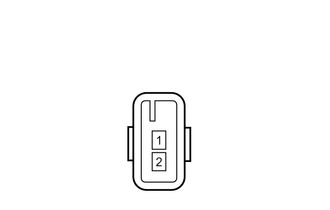
E144966

Disconnect the H1*1 and/or I1*2 front No. 1 speaker assembly connector.

*1: for RH

*2: for LH


b.

Measure the resistance according to the value(s) in the table below.

Standard Resistance:
Tester Connection Condition Specified Condition
1 - 2 Always 4 Ω


OK

4.CHECK HARNESS AND CONNECTOR (FRONT NO. 2 SPEAKER - FRONT NO. 1 SPEAKER)

NG

REPLACE FRONT NO. 1 SPEAKER ASSEMBLY

4.CHECK HARNESS AND CONNECTOR (FRONT NO. 2 SPEAKER - FRONT NO. 1 SPEAKER)

*1: for RH

*2: for LH


a.

Disconnect the H1*1 and/or I1*2 front No. 1 speaker assembly connector.


b.

Disconnect the G12*1 and/or G1*2 front No. 2 speaker assembly connector.


c.

Measure the resistance according to the value(s) in the table below.

Standard Resistance:
for RH:
Tester Connection Condition Specified Condition
H1-1- G12-2 (TWR+) Always Below 1 Ω
H1-2 - G12-4 (TWR-) Always Below 1 Ω
H1-1 - Body ground Always 10 kΩ or higher
H1-2 - Body ground Always 10 kΩ or higher

for LH:
Tester Connection Condition Specified Condition
I1-1 - G1-2 (TWL+) Always Below 1 Ω
I1-2 - G1-4 (TWL-) Always Below 1 Ω
I1-1 - Body ground Always 10 kΩ or higher
I1-2 - Body ground Always 10 kΩ or higher


OK

REPLACE RADIO RECEIVER ASSEMBLY

NG

REPAIR OR REPLACE HARNESS OR CONNECTOR

5.INSPECT FRONT NO. 2 SPEAKER ASSEMBLY
a.

Temporarily replace the front No. 2 speaker assembly with a new or normally functioning one (See page Audio / Visual / Telematics>AUDIO / VIDEO>INSTRUMENT PANEL SPEAKER>REMOVAL).

OK:

Malfunction disappears.


OK

6.CHECK HARNESS AND CONNECTOR (RADIO RECEIVER - FRONT NO. 2 SPEAKER)

NG

6.CHECK HARNESS AND CONNECTOR (RADIO RECEIVER - FRONT NO. 2 SPEAKER)
a.

Disconnect the G6 radio receiver assembly connector.


b.

Disconnect the G12*1 and/or G1*2 front No. 2 speaker assembly connector.

*1: for RH

*2: for LH


c.

Measure the resistance according to the value(s) in the table below.

Standard Resistance:
for RH:
Tester Connection Condition Specified Condition
G6-1 (FR+) - G12-1 (+) Always Below 1 Ω
G6-5 (FR-) - G12-3 (-) Always Below 1 Ω
G6-1 (FR+) - Body ground Always 10 kΩ or higher
G6-5 (FR-) - Body ground Always 10 kΩ or higher

for LH:
Tester Connection Condition Specified Condition
G6-2 (FL+) - G1-1 (+) Always Below 1 Ω
G6-6 (FL-) - G1-3 (-) Always Below 1 Ω
G6-2 (FL+) - Body ground Always 10 kΩ or higher
G6-6 (FL-) - Body ground Always 10 kΩ or higher


OK

REPLACE RADIO RECEIVER ASSEMBLY

NG

REPAIR OR REPLACE HARNESS OR CONNECTOR

7.INSPECT REAR NO. 1 SPEAKER ASSEMBLY
a.
E144966

Disconnect the J1*1 and/or K1*2 rear No. 1 speaker assembly connectors.

*1: for RH

*2: for LH


b.

Measure the resistance according to the value(s) in the table below.

Standard Resistance:
Tester Connection Condition Specified Condition
1 - 2 Always 4 Ω


OK

8.INSPECT REAR NO. 2 SPEAKER ASSEMBLY

NG

REPLACE REAR NO. 1 SPEAKER ASSEMBLY

8.INSPECT REAR NO. 2 SPEAKER ASSEMBLY
a.
E144966

Disconnect the W5*1 and/or W6*2 rear No. 2 speaker assembly connectors.

*1: for RH

*2: for LH


b.

Measure the resistance according to the value(s) in the table below.

Standard Resistance:
Tester Connection Condition Specified Condition
1 - 2 Always 4 Ω


OK

9.INSPECT RELAY (EQ RLY)

NG

REPLACE REAR NO. 2 SPEAKER ASSEMBLY

9.INSPECT RELAY (EQ RLY)
a.
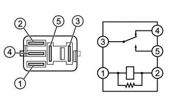
E195979

Remove the relay.


b.

Measure the resistance according to the value(s) in the table below.

Standard Resistance:
Tester Connection Condition Specified Condition
3 - 4 Battery voltage is not applied between terminals 1 and 2 Below 1 Ω
3 - 5 10 kΩ or higher
3 - 4 Battery voltage is applied to terminals 1 and 2 10 kΩ or higher
3 - 5 Below 1 Ω


OK

10.CHECK HARNESS AND CONNECTOR (RADIO RECEIVER - REAR NO. 1 SPEAKER)

NG

REPLACE RELAY

10.CHECK HARNESS AND CONNECTOR (RADIO RECEIVER - REAR NO. 1 SPEAKER)

*1: for RH

*2: for LH


a.

Disconnect the G5 radio receiver assembly connector.


b.

Disconnect the J1*1 and/or K1*2 rear No. 1 speaker assembly connector.


c.

Measure the resistance according to the value(s) in the table below.

Standard Resistance:
for RH:
Tester Connection Condition Specified Condition
G5-1 (RR+) - J1-1 Always Below 1 Ω
G5-1 (RR+) - Body ground Always 10 kΩ or higher

for LH:
Tester Connection Condition Specified Condition
G5-2 (RL+) - K1-1 Always Below 1 Ω
G5-2 (RL+) - Body ground Always 10 kΩ or higher


OK

11.CHECK HARNESS AND CONNECTOR (REAR NO. 1 SPEAKER - RELAY)

NG

REPAIR OR REPLACE HARNESS OR CONNECTOR

11.CHECK HARNESS AND CONNECTOR (REAR NO. 1 SPEAKER - RELAY)

*1: for RH

*2: for LH


a.

Disconnect the J1*1 and/or K1*2 rear No. 1 speaker assembly connector.


b.

Disconnect the relay connector.


c.

Measure the resistance according to the value(s) in the table below.

Standard Resistance:
for RH:
Tester Connection Condition Specified Condition
J1-2 - Relay-4 Always Below 1 Ω
J1-2 - Body ground Always 10 kΩ or higher

for LH:
Tester Connection Condition Specified Condition
K1-2 - Relay-4 Always Below 1 Ω
K1-2 - Body ground Always 10 kΩ or higher


OK

12.CHECK HARNESS AND CONNECTOR (REAR NO. 2 SPEAKER - RELAY)

NG

REPAIR OR REPLACE HARNESS OR CONNECTOR

12.CHECK HARNESS AND CONNECTOR (REAR NO. 2 SPEAKER - RELAY)

*1: for RH

*2: for LH


a.

Disconnect the W5*1 and/or W6*2 rear No. 2 speaker assembly connector.


b.

Disconnect the relay connector.


c.

Measure the resistance according to the value(s) in the table below.

Standard Resistance:
for RH:
Tester Connection Condition Specified Condition
W5-1 - Relay-3 Always Below 1 Ω
W5-1 - Body ground Always 10 kΩ or higher

for LH:
Tester Connection Condition Specified Condition
W6-1 - Relay-3 Always Below 1 Ω
W6-1 - Body ground Always 10 kΩ or higher


OK

13.CHECK HARNESS AND CONNECTOR (RADIO RECEIVER - REAR NO. 2 SPEAKER)

NG

REPAIR OR REPLACE HARNESS OR CONNECTOR

13.CHECK HARNESS AND CONNECTOR (RADIO RECEIVER - REAR NO. 2 SPEAKER)
a.

Disconnect the G5 radio receiver assembly connector.


b.

Disconnect the W5*1 and/or W6*2 rear No. 2 speaker assembly connector.

*1: for RH

*2: for LH


c.

Measure the resistance according to the value(s) in the table below.

Standard Resistance:
for RH:
Tester Connection Condition Specified Condition
G5-3 (RR-) - W5-2 Always Below 1 Ω
G5-3 (RR-) - Body ground Always 10 kΩ or higher

for LH:
Tester Connection Condition Specified Condition
G5-6 (RL-) - W6-2 Always Below 1 Ω
G5-6 (RL-) - Body ground Always 10 kΩ or higher


OK

REPLACE RADIO RECEIVER ASSEMBLY

NG

REPAIR OR REPLACE HARNESS OR CONNECTOR