Home › Audio / Visual / Telematics › AUDIO / VIDEO › AUDIO AND VISUAL SYSTEM › 2009.08–2013.08
RM1440E _56 Audio / Visual / Telematics _056150 AUDIO / VIDEO _0274026 AUDIO AND VISUAL SYSTEM J

AUDIO / VIDEO  AUDIO AND VISUAL SYSTEM  Microphone Circuit between Microphone and Radio Receiver  


DESCRIPTION

This circuit sends a microphone signal from the telephone microphone assembly to the radio receiver assembly.

This circuit also supplies power from the radio receiver assembly to the telephone microphone assembly.

WIRING DIAGRAM
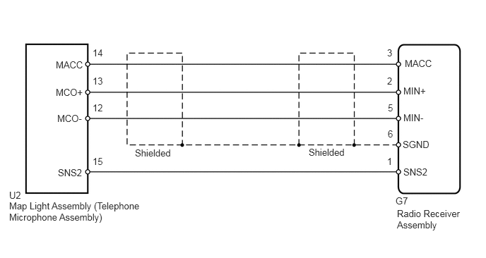
E195981E07
0.135,2.958 2.344,3.333 2.208,0.375 10 false Map Light Assembly (Telephone Microphone Assembly) 0.823,1.281 1.25,1.438 0.427,0.156 10 false MCO+ 0.844,1.667 1.26,1.823 0.417,0.156 10 false MCO- 0.823,0.875 1.26,1.031 0.438,0.156 10 false MACC 1.365,2.302 1.615,2.458 0.25,0.156 10 false 15 1.365,1.115 1.573,1.271 0.208,0.156 10 false 13 1.365,1.51 1.573,1.667 0.208,0.156 10 false 12 1.365,0.698 1.615,0.854 0.25,0.156 10 false 14 5.708,2.302 5.833,2.458 0.125,0.156 10 false 1 5.719,1.896 5.833,2.052 0.115,0.156 10 false 6 5.708,1.115 5.823,1.271 0.115,0.156 10 false 2 5.708,0.698 5.823,0.854 0.115,0.156 10 false 3 5.719,1.51 5.833,1.667 0.115,0.156 10 false 5 5.854,3.073 6.906,3.427 1.052,0.354 10 false Radio Receiver Assembly 5.948,1.26 6.385,1.417 0.438,0.156 10 false MIN+ 5.948,1.656 6.385,1.813 0.438,0.156 10 false MIN- 5.938,2.052 6.427,2.208 0.49,0.156 10 false SGND 5.969,0.854 6.406,1.01 0.438,0.156 10 false MACC 0.854,2.469 1.26,2.625 0.406,0.156 10 false SNS2 0.135,2.802 0.615,2.958 0.479,0.156 10 false U2 5.948,2.458 6.385,2.615 0.438,0.156 10 false SNS2 1.99,2.177 2.594,2.333 0.604,0.156 10 false Shielded 4.552,2.167 5.156,2.323 0.604,0.156 10 false Shielded 5.833,2.885 6.271,3.042 0.438,0.156 10 false G7

PROCEDURE

1.CHECK RADIO RECEIVER ASSEMBLY
a.
U181033E02
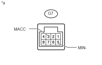
1.969,1.469 2.281,1.594 2.281,1.594 2.583,1.594 true 1.604,1.188 1.281,0.969 1.281,0.969 0.979,0.969 true 2.625,1.521 3.094,1.677 0.469,0.156 10 false MIN- 0.469,0.896 0.948,1.052 0.479,0.156 10 false MACC 1.615,0.365 1.865,0.521 0.25,0.156 10 false G7 0.042,0.01 0.51,0.167 0.469,0.156 10 false *a

Disconnect the G7 radio receiver assembly connector.


b.

Measure the resistance according to the value(s) in the table below.

Standard Resistance:
Tester Connection Condition Specified Condition
G7-5 (MIN-) - Body ground Always Below 1 Ω


c.

Measure the voltage according to the value(s) in the table below.

Standard Voltage:
Tester Connection Switch Condition Specified Condition
G7-3 (MACC) - Body ground Ignition switch ACC 4.75 to 5.25 V


Text in Illustration
*a Component without harness connected
(Radio Receiver Assembly)


OK

2.CHECK HARNESS AND CONNECTOR (RADIO RECEIVER - MAP LIGHT)

NG

REPLACE RADIO RECEIVER ASSEMBLY

2.CHECK HARNESS AND CONNECTOR (RADIO RECEIVER - MAP LIGHT)
a.

Disconnect the G7 radio receiver assembly connector.


b.

Disconnect the U2 map light assembly connector.


c.

Measure the resistance according to the value(s) in the table below.

Standard Resistance:
Tester Connection Condition Specified Condition
G7-3 (MACC) - U2-14 (MACC) Always Below 1 Ω
G7-2 (MIN+) - U2-13 (MCO+) Always Below 1 Ω
G7-5 (MIN-) - U2-12 (MCO-) Always Below 1 Ω
G7-1 (SNS2) - U2-15 (SNS2) Always Below 1 Ω
G7-3 (MACC) - Body ground Always 10 kΩ or higher
G7-2 (MIN+) - Body ground Always 10 kΩ or higher
G7-5 (MIN-) - Body ground Always 10 kΩ or higher
G7-1 (SNS2) - Body ground Always 10 kΩ or higher
G7-6 (SGND) - Body ground Always 10 kΩ or higher


OK

3.INSPECT MAP LIGHT ASSEMBLY

NG

REPAIR OR REPLACE HARNESS OR CONNECTOR

3.INSPECT MAP LIGHT ASSEMBLY
a.
E179201E16
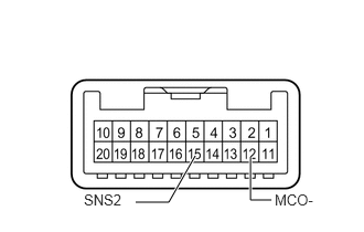
1.281,1.906 1.594,1.906 1.594,1.906 1.844,1.469 true 2.563,1.885 2.365,1.885 2.365,1.885 2.365,1.479 true 0.792,1.802 1.208,1.969 0.417,0.167 10 false SNS2 2.594,1.802 3.115,1.969 0.521,0.167 10 false MCO-

Remove the map light assembly (See page Vehicle Interior>LIGHTING (INT)>ROOM LIGHT(for Front)>REMOVAL).


b.

Measure the resistance according to the value(s) in the table below.

Standard Resistance:
Tester Connection Condition Specified Condition
15 (SNS2) - 12 (MCO-) Always Below 1 Ω


OK

4.CHECK MAP LIGHT ASSEMBLY

NG

5.REPLACE TELEPHONE MICROPHONE WITH ANOTHER AND CHECK
4.CHECK MAP LIGHT ASSEMBLY
a.
U181034E02
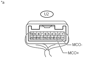
2.156,1.365 2.427,1.635 2.427,1.635 2.583,1.635 true 2.021,1.375 2.281,1.927 2.281,1.927 2.438,1.927 true 2.458,1.844 2.927,2.031 0.469,0.188 10 false MCO+ 0.031,0 0.5,0.188 0.469,0.188 10 false *a 2.615,1.542 3.083,1.729 0.469,0.188 10 false MCO- 1.594,0.427 1.927,0.615 0.333,0.188 10 false U2

Connect an oscilloscope to terminals U2-13 (MCO+) and U2-12 (MCO-) of the map light assembly connector.


b.

Check the waveform of the telephone microphone assembly using an oscilloscope.

Result
Result Proceed to
Waveform synchronized with the voice input to the telephone microphone assembly is output A
Waveform synchronized with the voice input to the telephone microphone assembly is not output B

Text in Illustration
*a Component with harness connected
(Map Light Assembly)


OK

PROCEED TO NEXT SUSPECTED AREA SHOWN IN PROBLEM SYMPTOMS TABLE

NG

5.REPLACE TELEPHONE MICROPHONE WITH ANOTHER AND CHECK
a.

Replace the telephone microphone assembly with a normal one (See page Audio / Visual / Telematics>AUDIO / VIDEO>MICROPHONE AMPLIFIER>REMOVAL).


b.

Check if the same problem occurs again.

OK:

Malfunction disappears.


OK

END (TELEPHONE MICROPHONE IS FAULTY)

NG