AUDIO / VIDEO AUDIO AND VISUAL SYSTEM Multi-media Interface ECU Communication Error
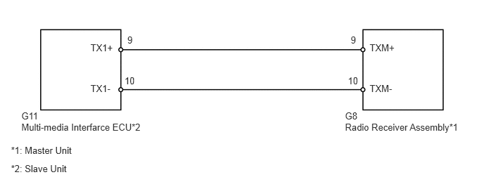
WIRING DIAGRAM
PROCEDURE
Enter the diagnostic mode.
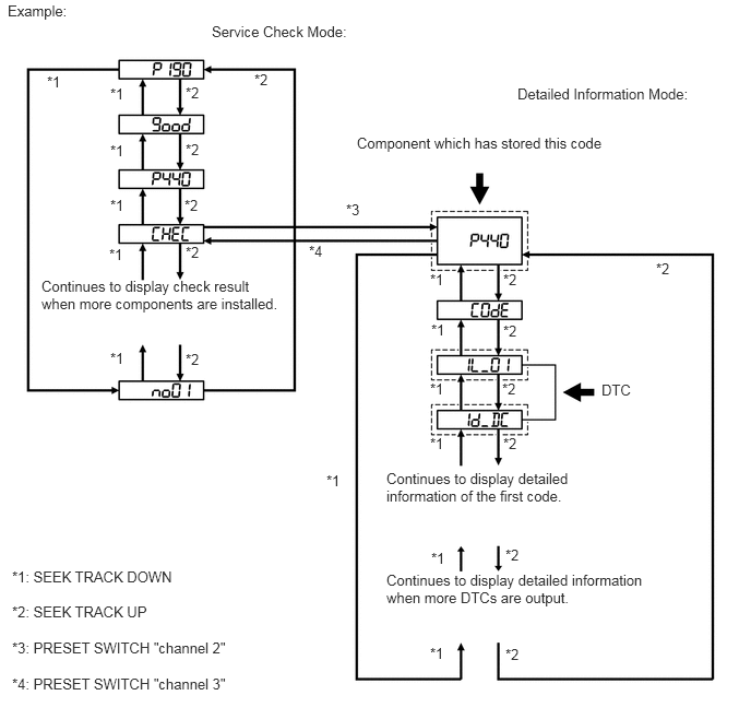
Press preset switch "channel 2" to change to "Detailed Information Mode".
Identify the component shown by the sub-code.
- HINT:
- ·
"190 (radio receiver assembly)" is the component shown by the sub-code in the example shown in the illustration.
·For details of the DTC display, refer to DTC Check/Clear (See page Audio / Visual / Telematics>AUDIO / VIDEO>AUDIO AND VISUAL SYSTEM>DTC CHECK / CLEAR).
NEXT
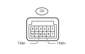
Disconnect the G8 radio receiver assembly connector.
Measure the resistance according to the value(s) in the table below.
- Standard Resistance:
Tester Connection Condition Specified Condition G8-9 (TXM+) - G8-10 (TXM-) Always 60 to 80 Ω
OK
NG
- HINT:
- ·
Start the check from the circuit that is near the component shown by the sub-code first.
·For details of the connectors, refer to Terminals of ECU (See page Audio / Visual / Telematics>AUDIO / VIDEO>AUDIO AND VISUAL SYSTEM>TERMINALS OF ECU).
Referring to the wiring diagram, check the AVC-LAN circuit between the multi-media interface ECU and component shown by the sub-code.
Disconnect all connectors between the multi-media interface ECU and component shown by the sub-code.
Check for an open or short in the AVC-LAN circuit between the multi-media interface ECU and component shown by the sub-code.
- OK:
There is no open or short circuit.
OK
NG
Replace the component shown by the sub-code with a known good one and check if the same problem occurs again.
- OK:
Malfunction disappears.
OK
NG