Home › Audio / Visual / Telematics › PARK ASSIST / MONITORING › TOYOTA PARKING ASSIST-SENSOR SYSTEM › from 2013.08
RM1440E _56 Audio / Visual / Telematics _056151 PARK ASSIST / MONITORING _0274043 TOYOTA PARKING ASSIST-SENSOR SYSTEM J

PARK ASSIST / MONITORING  TOYOTA PARKING ASSIST-SENSOR SYSTEM  Clearance Sonar Main Switch Circuit  


DESCRIPTION

When the back sonar or clearance sonar switch assembly turns on, the on signal is input into the clearance warning ECU assembly.

WIRING DIAGRAM
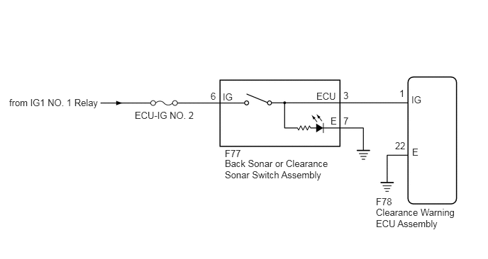
E282888E03
5.521,3.042 6.906,3.427 1.385,0.385 10 false Clearance Warning ECU Assembly 5.521,2.885 5.896,3.115 0.375,0.229 10 false F78 3.302,2.323 5.021,2.677 1.719,0.354 10 false Back Sonar or Clearance Sonar Switch Assembly 0.135,1.427 1.479,1.656 1.344,0.229 10 false from IG1 NO. 1 Relay 3.302,2.177 3.677,2.406 0.375,0.229 10 false F77 4.646,1.333 5.021,1.563 0.375,0.229 10 false ECU 6.042,1.385 6.417,1.615 0.375,0.229 10 false IG 6.052,2.156 6.24,2.385 0.188,0.229 10 false E 5.802,2.063 6.073,2.292 0.271,0.229 10 false 22 5.865,1.292 6.031,1.49 0.167,0.198 10 false 1 5.042,1.323 5.208,1.521 0.167,0.198 10 false 3 3.094,1.333 3.26,1.531 0.167,0.198 10 false 6 5.042,1.698 5.208,1.896 0.167,0.198 10 false 7 3.271,1.344 3.646,1.573 0.375,0.229 10 false IG 4.854,1.698 5.031,1.906 0.177,0.208 10 false E 1.979,1.615 3,1.833 1.021,0.219 10 false ECU-IG NO. 2

CAUTION / NOTICE / HINT

NOTICE:

Inspect the fuses for circuits related to this system before performing the following inspection procedure.


PROCEDURE

1.INSPECT BACK SONAR OR CLEARANCE SONAR SWITCH ASSEMBLY
a.

Remove the back sonar or clearance sonar switch assembly (See page Audio / Visual / Telematics>PARK ASSIST / MONITORING>CLEARANCE SONAR MAIN SWITCH>REMOVAL).


b.

Inspect the back sonar or clearance sonar switch assembly (See page Audio / Visual / Telematics>PARK ASSIST / MONITORING>CLEARANCE SONAR MAIN SWITCH>INSPECTION).


OK

2.CHECK HARNESS AND CONNECTOR (BACK SONAR OR CLEARANCE SONAR SWITCH ASSEMBLY - BATTERY AND BODY GROUND)

NG

REPLACE BACK SONAR OR CLEARANCE SONAR SWITCH ASSEMBLY

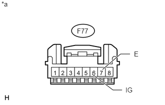
2.CHECK HARNESS AND CONNECTOR (BACK SONAR OR CLEARANCE SONAR SWITCH ASSEMBLY - BATTERY AND BODY GROUND)
a.
U180706E02
1.917,1.542 2.354,1.875 2.354,1.875 2.542,1.875 true 2.135,1.448 2.51,1.125 2.51,1.125 2.708,1.125 true 0.031,0 0.323,0.177 0.292,0.177 10 false *a 1.604,0.563 1.958,0.771 0.354,0.208 10 false F77 2.615,1.792 2.906,1.969 0.292,0.177 10 false IG 2.792,1.042 2.917,1.229 0.125,0.188 10 false E

Disconnect the F77 back sonar or clearance sonar switch assembly connector.


b.

Measure the voltage according to the value(s) in the table below.

Standard Voltage:
Tester Connection Switch Condition Specified Condition
F77-6 (IG) - Body ground Ignition switch ON 11 to 14 V
Ignition switch off Below 1 V


c.

Measure the resistance according to the value(s) in the table below.

Standard Resistance:
Tester Connection Condition Specified Condition
F77-7 (E) - Body ground Always Below 1 Ω


Text in Illustration
*a Front view of wire harness connector
(to Back Sonar or Clearance Sonar Switch Assembly)


OK

3.CHECK HARNESS AND CONNECTOR (BACK SONAR OR CLEARANCE SONAR SWITCH ASSEMBLY - CLEARANCE WARNING ECU ASSEMBLY)

NG

REPAIR OR REPLACE HARNESS OR CONNECTOR

3.CHECK HARNESS AND CONNECTOR (BACK SONAR OR CLEARANCE SONAR SWITCH ASSEMBLY - CLEARANCE WARNING ECU ASSEMBLY)
a.

Disconnect the F77 back sonar or clearance sonar switch assembly connector.


b.

Disconnect the F78 clearance warning ECU assembly connector.


c.

Measure the resistance according to the value(s) in the table below.

Standard Resistance:
Tester Connection Condition Specified Condition
F77-3 (ECU) - F78-1 (IG) Always Below 1 Ω
F77-3 (ECU) - Body ground Always 10 kΩ or higher


OK

4.CHECK HARNESS AND CONNECTOR (CLEARANCE WARNING ECU ASSEMBLY - BODY GROUND)

NG

REPAIR OR REPLACE HARNESS OR CONNECTOR

4.CHECK HARNESS AND CONNECTOR (CLEARANCE WARNING ECU ASSEMBLY - BODY GROUND)
a.

Disconnect the F78 clearance warning ECU assembly connector.


b.

Measure the resistance according to the value(s) in the table below.

Standard Resistance:
Tester Connection Condition Specified Condition
F78-22 (E) - Body ground Always Below 1 Ω


OK

NG

REPAIR OR REPLACE HARNESS OR CONNECTOR