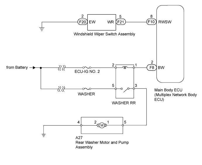
WIPER AND WASHER SYSTEM > Rear Washer does not Operate |
| 1.READ VALUE USING TECHSTREAM (WINDSHIELD WIPER SWITCH) |
Use the Data List to check if the rear washer is functioning properly (Click here).
| Tester Display | Measurement Item/Range | Normal Condition | Diagnostic Note |
| Rear Washer SW Signal | Rear washer switch / ON or OFF | ON: Rear washer switch on OFF: Rear washer switch off | - |
|
| ||||
| OK | |
 |
| 2.PERFORM ACTIVE TEST USING TECHSTREAM (WASHER RR RELAY) |
Using the Techstream, perform the Active Test (Click here).
| Tester Display | Test Part | Control Range | Diagnostic Note |
| Rear Wiper Washer Motor Relay | WASHER RR relay operation | ON/OFF | - |
|
| ||||
| OK | ||
 | ||
| ||
| 3.INSPECT WASHER RR RELAY |
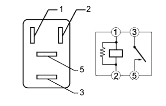 |
Remove the WASHER RR relay from the engine room relay block, junction block.
Measure the resistance according to the value(s) in the table below.
| Tester Connection | Condition | Specified Condition |
| 3 - 5 | Battery voltage is not applied to terminals 1 and 2 | 10 kΩ or higher |
| Battery voltage is applied to terminals 1 and 2 | Below 1 Ω |
|
| ||||
| OK | |
|
| 4.CHECK HARNESS AND CONNECTOR (BATTERY - WASHER RR RELAY) |
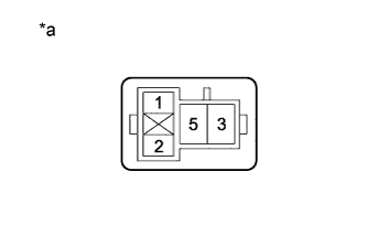 |
Remove the WASHER RR relay from the engine room relay block, junction block.
Measure the voltage according to the value(s) in the table below.
| Tester Connection | Switch Condition | Specified Condition |
| RR WASHER relay terminal 2 - Body ground | Ignition switch ON | 11 to 14 V |
| RR WASHER relay terminal 2 - Body ground | Ignition switch off | Below 1 V |
| RR WASHER relay terminal 5 - Body ground | Ignition switch ON | 11 to 14 V |
| RR WASHER relay terminal 5 - Body ground | Ignition switch off | Below 1 V |
| *a | Front view of wire harness connector (to WASHER RR Relay) |
|
| ||||
| OK | |
|
| 5.CHECK HARNESS AND CONNECTOR (WASHER RR RELAY - MAIN BODY ECU) |
Remove the WASHER RR relay from the engine room relay block, junction block.
Disconnect the F8 main body ECU connector.
Measure the resistance according to the value(s) in the table below.
| Tester Connection | Condition | Specified Condition |
| F8-2 (BW) - WASHER RR relay terminal 1 | Always | Below 1 Ω |
| F8-2 (BW) - Body ground | Always | 10 kΩ or higher |
|
| ||||
| OK | |
|
| 6.INSPECT REAR WASHER MOTOR AND PUMP ASSEMBLY |
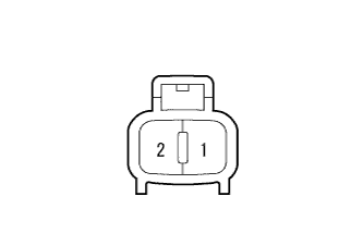 |
Remove the rear washer motor and pump (Click here).
Apply battery voltage to the rear wiper motor and check the operation of the rear wiper motor.
| Measurement Condition | Specified Condition |
| Battery positive (+) → 1 Battery negative (-) → 2 | Rear washer motor operation is normal |
|
| ||||
| OK | |
|
| 7.CHECK WIRE HARNESS (REAR WASHER MOTOR AND PUMP ASSEMBLY) |
Disconnect the A27 level warning switch connector.
Measure the resistance according to the value(s) in the table below.
| Tester Connection | Condition | Specified Condition |
| A27-5 - 1 | Always | Below 1 Ω |
| A27-4 - 2 | Always | Below 1 Ω |
| A27-5 - Body ground | Always | 10 kΩ or higher |
| A27-4 - Body ground | Always | 10 kΩ or higher |
|
| ||||
| OK | |
|
| 8.CHECK HARNESS AND CONNECTOR (REAR WASHER MOTOR AND PUMP ASSEMBLY - WASHER RR RELAY AND BODY GROUND) |
Disconnect the A27 rear washer motor connector.
Remove the WASHER RR relay from the engine room relay block, junction block.
Measure the resistance according to the value(s) in the table below.
| Tester Connection | Condition | Specified Condition |
| A27-5 - WASHER RR relay terminal 3 | Always | Below 1 Ω |
| A27-4 - Body ground | Always | Below 1 Ω |
| A27-5 - Body ground | Always | 10 kΩ or higher |
|
| ||||
| OK | ||
| ||
| ||
| 9.INSPECT WINDSHIELD WIPER SWITCH ASSEMBLY |
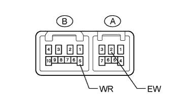 |
Remove the windshield wiper switch (Click here).
Measure the resistance according to the value(s) in the table below.
| Tester Connection | Switch Condition | Specified Condition |
| B-5 (WR) - A-2 (EW) | Rear washer switch on | Below 1 Ω |
| B-5 (WR) - A-2 (EW) | Rear washer switch off | 10 kΩ or higher |
|
| ||||
| OK | |
|
| 10.CHECK HARNESS AND CONNECTOR (WINDSHIELD WIPER SWITCH ASSEMBLY - MAIN BODY ECU AND BODY GROUND) |
Disconnect the F20 and F21 windshield wiper switch connectors.
Disconnect the F10 main body ECU connector.
Measure the resistance according to the value(s) in the table below.
| Tester Connection | Condition | Specified Condition |
| F21-5 (WR) - F10-8 (RWSW) | Always | Below 1 Ω |
| F20-2 (EW) - Body ground | Always | Below 1 Ω |
| F21-5 (WR) - Body ground | Always | 10 kΩ or higher |
|
| ||||
| OK | ||
| ||
| ||

