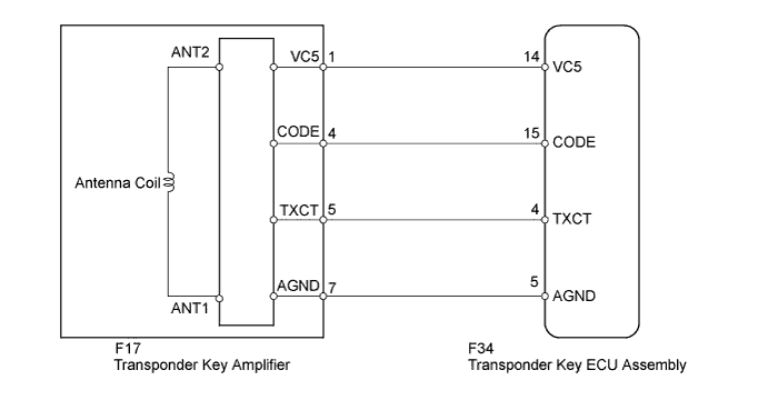
DTC B2796 No Communication in Immobiliser System |
DTC B2798 Communication Malfunction No. 2 |
| DTC Code | DTC Detection Condition | Trouble Area |
| B2796 | The key code cannot be transmitted. |
|
| B2798 | Key code identification cannot be completed within the specified time. | Key |
| 1.CLEAR DTC |
Clear the DTCs (Click here).
| NEXT | |
 |
| 2.CHECK FOR DTC |
Check for DTCs (Click here).
|
| ||||
| OK | ||
 | ||
| ||
| 3.READ VALUE USING TECHSTREAM (ENGINE IMMOBILISER SYSTEM) |
Use the Data List to check if the engine immobiliser system is functioning properly (Click here).
| Tester Display | Measurement Item/Range | Normal Condition | Diagnostic Note |
| Immobiliser | Immobiliser system status / Set or Unset | Set: No key in ignition key cylinder Unset: Key inserted in ignition key cylinder | - |
|
| ||||
| OK | ||
| ||
| ||
| 4.CHECK WHETHER ENGINE STARTS WITH OTHER KEYS |
Check if the engine starts with an already registered vehicle key.
|
| ||||
| OK | ||
| ||
| ||
| 5.CHECK HARNESS AND CONNECTOR (TRANSPONDER KEY ECU - TRANSPONDER KEY AMPLIFIER) |
Disconnect the F34 ECU connector.
Disconnect the F17 amplifier connector.
Measure the resistance according to the value(s) in the table below.
| Tester Connection | Condition | Specified Condition |
| F34-14 (VC5) - F17-1 (VC5) | Always | Below 1 Ω |
| F34-15 (CODE) - F17-4 (CODE) | ||
| F34-4 (TXCT) - F17-5 (TXCT) | ||
| F34-5 (AGND) - F17-7 (AGND) | ||
| F34-14 (VC5) or F17-1 (VC5) - Body ground | Always | 10 kΩ or higher |
| F34-15 (CODE) or F17-4 (CODE) - Body ground | ||
| F34-4 (TXCT) or F17-5 (TXCT) - Body ground | ||
| F34-5 (AGND) or F17-7 (AGND) - Body ground |
|
| ||||
| OK | |
|
| 6.REPLACE TRANSPONDER KEY AMPLIFIER |
Temporarily replace the transponder key amplifier with a new or normally functioning one (Click here).
| NEXT | |
|
| 7.CHECK WHETHER ENGINE STARTS |
Check that the engine starts normally.
|
| ||||
| OK | ||
| ||
| ||

