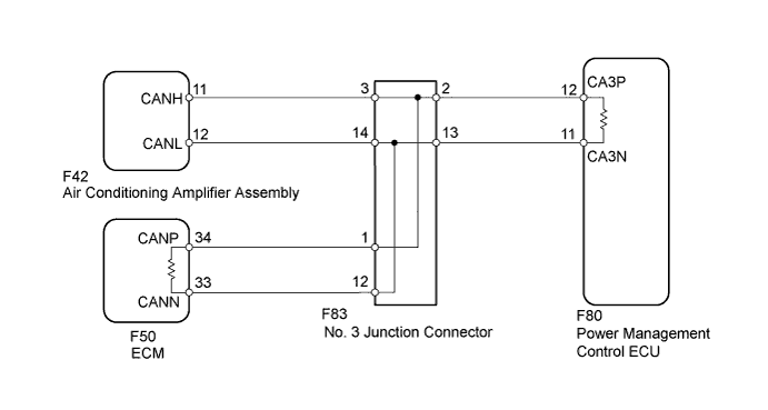
DTC U1002 Lost Communication with Gateway Module (Power Management2) |
| DTC Code | DTC Detection Condition | Trouble Area |
| U1002 | Lost communication with the gateway module (Power Management2). |
|
| 1.DISCONNECT CABLE FROM NEGATIVE BATTERY TERMINAL |
Disconnect the cable from the negative (-) battery terminal before measuring the resistances of the main wire and branch wire.
| NEXT | |
 |
| 2.CHECK FOR CAN BUS WIRE (MAIN WIRE FOR DISCONNECTION, BUS LINE FOR SHORT CIRCUIT) |
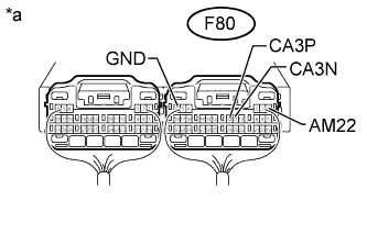 |
Measure the resistance according to the value(s) in the table below.
| Tester Connection | Switch Condition | Specified Condition | Resistance: Malfunction |
| F80-12 (CA3P) - F80-11 (CA3N) | Ignition switch off | 54 to 69 Ω | Below 54 Ω: Short in line |
| Ignition switch off | Higher than 69 Ω: Open in CAN main bus line | ||
| F80-12 (CA3P) - F80-1 (AM22) | Ignition switch off | 6 kΩ or higher | Below 6 kΩ: +B short |
| F80-11 (CA3N) - F80-1 (AM22) | Ignition switch off | 6 kΩ or higher | Below 6 kΩ: +B short |
| F80-12 (CA3P) - F80-6 (GND) | Ignition switch off | 200 Ω or higher | Below 200 Ω: Ground short |
| F80-11 (CA3N) - F80-6 (GND) | Ignition switch off | 200 Ω or higher | Below 200 Ω: Ground short |
| *a | Component with harness connected (Power Management Control ECU) |
| Result | Proceed to |
| NG - Open in CAN main bus line | A |
| NG - Short in line - +B short - Ground short | B |
| OK | C |
|
| ||||
|
| ||||
| A | |
|
| 3.CHECK FOR OPEN IN CAN BUS MAIN WIRE (NO. 3 JUNCTION CONNECTOR - ECM) |
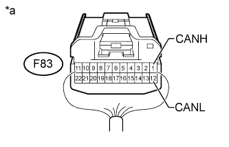 |
Disconnect the F83 No. 3 junction connector connector.
Measure the resistance according to the value(s) in the table below.
| Tester Connection | Switch Condition | Specified Condition |
| F83-1 (CANH) - F83-12 (CANL) | Ignition switch off | 108 to 132 Ω |
| *a | Rear view of wire harness connector (to No. 3 Junction Connector) |
|
| ||||
| OK | |
|
| 4.CHECK FOR OPEN IN CAN BUS MAIN WIRE (NO. 3 JUNCTION CONNECTOR - POWER MANAGEMENT CONTROL ECU) |
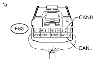 |
Measure the resistance according to the value(s) in the table below.
| Tester Connection | Switch Condition | Specified Condition |
| F83-2 (CANH) - F83-13 (CANL) | Ignition switch off | 108 to 132 Ω |
| *a | Rear view of wire harness connector (to No. 3 Junction Connector) |
|
| ||||
| OK | ||
 | ||
| ||
| 5.CONNECT CONNECTOR |
Reconnect the F83 No. 3 junction connector connector.
| NEXT | |
|
| 6.CHECK FOR OPEN IN CAN BUS MAIN WIRE (ECM - NO. 3 JUNCTION CONNECTOR) |
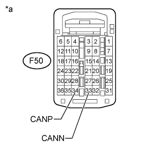 |
Disconnect the F50 ECM connector.
Measure the resistance according to the value(s) in the table below.
| Tester Connection | Switch Condition | Specified Condition |
| F50-34 (CANP) - F50-33 (CANN) | Ignition switch off | 108 to 132 Ω |
| *a | Rear view of wire harness connector (to ECM) |
|
| ||||
| OK | ||
| ||
| ||
| 7.CONNECT CONNECTOR |
Reconnect the F83 No. 3 junction connector connector.
| NEXT | |
|
| 8.CHECK FOR OPEN IN CAN BUS MAIN WIRE (POWER MANAGEMENT CONTROL ECU - NO. 3 JUNCTION CONNECTOR) |
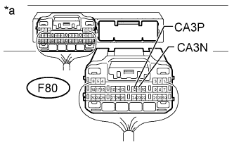 |
Disconnect the F80 power management control ECU connector.
Measure the resistance according to the value(s) in the table below.
| Tester Connection | Switch Condition | Specified Condition |
| F80-12 (CA3P) - F80-11 (CA3N) | Ignition switch off | 108 to 132 Ω |
| *a | Rear view of wire harness connector (to Power Management Control ECU) |
|
| ||||
| OK | ||
| ||
| ||
| 9.CHECK FOR SHORT IN CAN BUS WIRES (NO. 3 JUNCTION CONNECTOR - AIR CONDITIONING AMPLIFIER ASSEMBLY) |
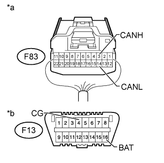 |
Disconnect the F83 No. 3 junction connector connector.
Measure the resistance according to the value(s) in the table below.
| Tester Connection | Switch Condition | Specified Condition |
| F83-3 (CANH) - F83-14 (CANL) | Ignition switch off | 200 Ω or higher |
| F83-3 (CANH) - F13-4 (CG) | Ignition switch off | 200 Ω or higher |
| F83-14 (CANL) - F13-4 (CG) | Ignition switch off | 200 Ω or higher |
| F83-3 (CANH) - F13-16 (BAT) | Ignition switch off | 6 kΩ or higher |
| F83-14 (CANL) - F13-16 (BAT) | Ignition switch off | 6 kΩ or higher |
| *a | Rear view of wire harness connector (to No. 3 Junction Connector) |
| *b | Front view of DLC3 |
|
| ||||
| OK | |
|
| 10.CHECK FOR SHORT IN CAN BUS WIRES (NO. 3 JUNCTION CONNECTOR - ECM) |
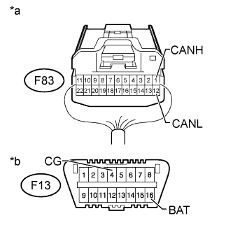 |
Measure the resistance according to the value(s) in the table below.
| Tester Connection | Switch Condition | Specified Condition |
| F83-1 (CANH) - F83-12 (CANL) | Ignition switch off | 108 to 132 Ω |
| F83-1 (CANH) - F13-4 (CG) | Ignition switch off | 200 Ω or higher |
| F83-12 (CANL) - F13-4 (CG) | Ignition switch off | 200 Ω or higher |
| F83-1 (CANH) - F13-16 (BAT) | Ignition switch off | 6 kΩ or higher |
| F83-12 (CANL) - F13-16 (BAT) | Ignition switch off | 6 kΩ or higher |
| *a | Rear view of wire harness connector (to No. 3 Junction Connector) |
| *b | Front view of DLC3 |
|
| ||||
| OK | |
|
| 11.CHECK FOR SHORT IN CAN BUS WIRES (NO. 3 JUNCTION CONNECTOR - POWER MANAGEMENT CONTROL ECU) |
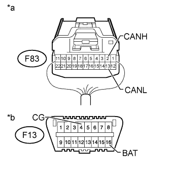 |
Measure the resistance according to the value(s) in the table below.
| Tester Connection | Switch Condition | Specified Condition |
| F83-2 (CANH) - F83-13 (CANL) | Ignition switch off | 108 to 132 Ω |
| F83-2 (CANH) - F13-4 (CG) | Ignition switch off | 200 Ω or higher |
| F83-13 (CANL) - F13-4 (CG) | Ignition switch off | 200 Ω or higher |
| F83-2 (CANH) - F13-16 (BAT) | Ignition switch off | 6 kΩ or higher |
| F83-13 (CANL) - F13-16 (BAT) | Ignition switch off | 6 kΩ or higher |
| *a | Rear view of wire harness connector (to No. 3 Junction Connector) |
| *b | Front view of DLC3 |
|
| ||||
| OK | ||
| ||
| ||
| 12.CONNECT CONNECTOR |
Reconnect the F83 No. 3 junction connector connector.
| NEXT | |
|
| 13.CHECK FOR SHORT IN CAN BUS WIRES (AIR CONDITIONING AMPLIFIER ASSEMBLY) |
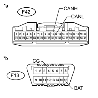 |
Disconnect the F42 air conditioning amplifier assembly connector.
Measure the resistance according to the value(s) in the table below.
| Tester Connection | Switch Condition | Specified Condition |
| F42-11 (CANH) - F42-12 (CANL) | Ignition switch off | 54 to 69 Ω |
| F42-11 (CANH) - F13-4 (CG) | Ignition switch off | 200 Ω or higher |
| F42-12 (CANL) - F13-4 (CG) | Ignition switch off | 200 Ω or higher |
| F42-11 (CANH) - F13-16 (BAT) | Ignition switch off | 6 kΩ or higher |
| F42-12 (CANL) - F13-16 (BAT) | Ignition switch off | 6 kΩ or higher |
| *a | Front view of wire harness connector (to Air Conditioning Amplifier Assembly) |
| *b | Front view of DLC3 |
|
| ||||
| OK | ||
| ||
| ||
| 14.CONNECT CONNECTOR |
Reconnect the F83 No. 3 junction connector connector.
| NEXT | |
|
| 15.CHECK FOR SHORT IN CAN BUS WIRES (ECM) |
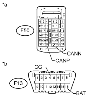 |
Disconnect the F50 ECM connector.
Measure the resistance according to the value(s) in the table below.
| Tester Connection | Switch Condition | Specified Condition |
| F50-34 (CANP) - F50-33 (CANN) | Ignition switch off | 108 to 132 Ω |
| F50-34 (CANP) - F13-4 (CG) | Ignition switch off | 200 Ω or higher |
| F50-33 (CANN) - F13-4 (CG) | Ignition switch off | 200 Ω or higher |
| F50-34 (CANP) - F13-16 (BAT) | Ignition switch off | 6 kΩ or higher |
| F50-33 (CANN) - F13-16 (BAT) | Ignition switch off | 6 kΩ or higher |
| *a | Rear view of wire harness connector (to ECM) |
| *b | Front view of DLC3 |
|
| ||||
| OK | ||
| ||
| ||
| 16.CONNECT CONNECTOR |
Reconnect the F83 No. 3 junction connector connector.
| NEXT | |
|
| 17.CHECK FOR SHORT IN CAN BUS WIRES (POWER MANAGEMENT CONTROL ECU) |
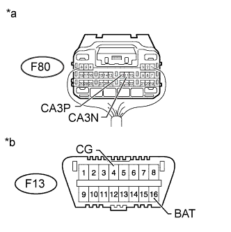 |
Disconnect the F80 power management control ECU connector.
Measure the resistance according to the value(s) in the table below.
| Tester Connection | Switch Condition | Specified Condition |
| F80-12 (CA3P) - F80-11 (CA3N) | Ignition switch off | 108 to 132 Ω |
| F80-12 (CA3P) - F13-4 (CG) | Ignition switch off | 200 Ω or higher |
| F80-11 (CA3N) - F13-4 (CG) | Ignition switch off | 200 Ω or higher |
| F80-12 (CA3P) - F13-16 (BAT) | Ignition switch off | 6 kΩ or higher |
| F80-11 (CA3N) - F13-16 (BAT) | Ignition switch off | 6 kΩ or higher |
| *a | Rear view of wire harness connector (to Power Management Control ECU) |
| *b | Front view of DLC3 |
|
| ||||
| OK | ||
| ||
| ||
| 18.CHECK HARNESS AND CONNECTOR (POWER MANAGEMENT CONTROL ECU - BATTERY AND GROUND) |
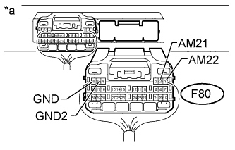 |
Connect the cable to the negative (-) battery terminal.
Disconnect the F80 power management control ECU connector.
Measure the resistance according to the value(s) in the table below.
| Tester Connection | Condition | Specified Condition |
| F80-5 (GND2) - Body ground | Always | Below 1 Ω |
| F80-6 (GND) - Body ground | Always | Below 1 Ω |
Measure the voltage according to the value(s) in the table below.
| Tester Connection | Condition | Specified Condition |
| F80-1 (AM22) - Body ground | Always | 11 to 14 V |
| F80-2 (AM21) - Body ground | Always | 11 to 14 V |
| *a | Rear view of wire harness connector (to Power Management Control ECU) |
|
| ||||
| OK | ||
| ||
| ||

