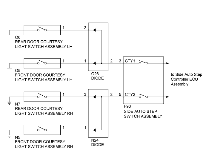
AUTOMATIC RUNNING BOARD SYSTEM > Door Courtesy Switch Circuit |
| 1.READ VALUE USING TECHSTREAM (DOOR COURTESY LIGHT SWITCH) |
Using the Techstream, read the Data List (Click here).
| Tester Display | Measurement Item/Range | Normal Condition | Diagnostic Note |
| RR Door Courtesy SW | Rear door courtesy light switch RH signal / ON or OFF | ON: Rear door RH open OFF: Rear door RH closed | - |
| RL Door Courtesy SW | Rear door courtesy light switch LH signal / ON or OFF | ON: Rear door LH open OFF: Rear door LH closed | - |
| FR Door Courtesy SW | Front door courtesy light switch RH signal / ON or OFF | ON: Front door RH closed OFF: Front door RH open | - |
| FL Door Courtesy SW | Front door courtesy light switch LH signal / ON or OFF | ON: Front door LH closed OFF: Front door LH open | - |
|
| ||||
| OK | |
 |
| 2.CHECK HARNESS AND CONNECTOR (DOOR COURTESY LIGHT SWITCH - DIODE) |
for LH
Disconnect the O5 and O6 door courtesy light switch connectors.
Disconnect the O26 diode connector.
for RH
Disconnect the N5 and N7 door courtesy light switch connectors.
Disconnect the N24 diode connector.
Measure the resistance according to the value(s) in the table below.
| Tester Connection | Condition | Specified Condition |
| O5-1 - O26-1 | Always | Below 1 Ω |
| O6-1 - O26-3 | Always | Below 1 Ω |
| Tester Connection | Condition | Specified Condition |
| N5-1 - N24-1 | Always | Below 1 Ω |
| N7-1 - N24-3 | Always | Below 1 Ω |
| Tester Connection | Condition | Specified Condition |
| O5-1 - Body ground | Always | 10 kΩ or higher |
| O6-1 - Body ground | Always | 10 kΩ or higher |
| Tester Connection | Condition | Specified Condition |
| N5-1 - Body ground | Always | 10 kΩ or higher |
| N7-1 - Body ground | Always | 10 kΩ or higher |
|
| ||||
| OK | |
|
| 3.CHECK HARNESS AND CONNECTOR (DIODE - SIDE AUTO STEP SWITCH) |
Disconnect the F90 side auto step switch assembly connector.
Measure the resistance according to the value(s) in the table below.
| Tester Connection | Condition | Specified Condition |
| O26-2 - F90-3 (CTY1) | Always | Below 1 Ω |
| Tester Connection | Condition | Specified Condition |
| N24-2 - F90-5 (CTY2) | Always | Below 1 Ω |
| Tester Connection | Condition | Specified Condition |
| O26-2 - Body ground | Always | 10 kΩ or higher |
| Tester Connection | Condition | Specified Condition |
| N24-2 - Body ground | Always | 10 kΩ or higher |
|
| ||||
| OK | |
|
| 4.REPLACE DIODE |
Replace the diode on the malfunctioning side with a new or correctly functioning diode.
| NEXT | |
|
| 5.CHECK AUTOMATIC RUNNING BOARD OPERATION |
Check that the automatic running board functions normally (Click here).
|
| ||||
| OK | ||
 | ||
| ||
