 |
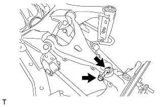
Temporarily tighten the rear upper control arm assembly LH to the rear axle carrier sub-assembly with the bolt and new nut.
REAR AXLE CARRIER > INSTALLATION |
| 1. INSTALL REAR AXLE CARRIER SUB-ASSEMBLY LH |
Using a jack and wooden block, jack up the rear axle carrier sub-assembly LH to replicate the standard vehicle height conditions.
| 2. TEMPORARILY TIGHTEN REAR UPPER CONTROL ARM ASSEMBLY LH |
|
Temporarily tighten the rear upper control arm assembly LH to the rear axle carrier sub-assembly with the bolt and new nut.
| 3. TEMPORARILY TIGHTEN REAR NO. 1 SUSPENSION ARM ASSEMBLY LH |
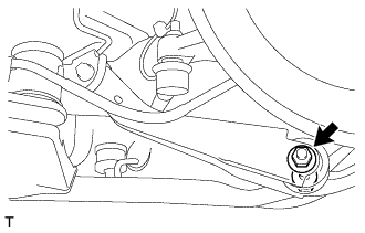 |
Temporarily tighten the rear No. 1 suspension arm assembly LH to the rear axle carrier sub-assembly with the bolt and new nut.
| 4. TEMPORARILY TIGHTEN REAR NO. 2 SUSPENSION ARM ASSEMBLY LH |
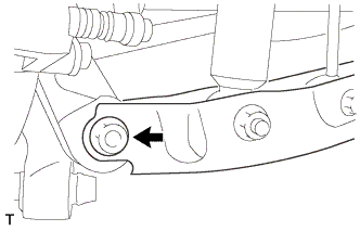 |
Temporarily tighten the rear No. 2 suspension arm assembly LH to the rear axle carrier sub-assembly with the bolt and new nut.
| 5. INSTALL TOE CONTROL LINK SUB-ASSEMBLY LH |
Install the nut and the toe control link sub-assembly LH to the rear axle carrier sub-assembly.
Install the cotter pin.
| 6. TEMPORARILY TIGHTEN STABILIZER LINK SUB-ASSEMBLY (for LH Side) |
Temporarily install the rear stabilizer link sub-assembly to the rear No. 2 suspension arm assembly LH with the bolt and new nut.
| 7. INSTALL REAR HEIGHT CONTROL SENSOR SUB-ASSEMBLY LH (w/ HID Headlight System) |
Install the rear height control sensor sub-assembly LH to the rear No. 2 suspension arm assembly LH with the nut.
| 8. REMOVE NO. 3 PARKING BRAKE CABLE ASSEMBLY |
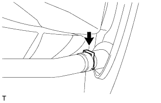 |
Install the clip and the No. 3 parking brake cable assembly to the parking brake plate sub-assembly.
| 9. REASSEMBLY PARKING BRAKE ASSEMBLY |
| 10. STABILIZE SUSPENSION |
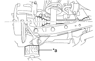 |
Jack up the axle carrier, with a wooden block placed between the jack and axle carrier, to apply load to the suspension so that the rear drive shaft assembly becomes level.
| *a | Wooden Block |
| 11. FULLY TIGHTEN REAR UPPER CONTROL ARM ASSEMBLY LH |
|
Fully tighten the bolt.
| 12. REMOVE REAR NO. 1 SUSPENSION ARM ASSEMBLY LH |
|
Fully tighten the bolt.
| 13. INSTALL REAR NO. 2 SUSPENSION ARM ASSEMBLY LH |
|
Fully tighten the bolt.
| 14. INSTALL REAR AXLE HUB AND BEARING ASSEMBLY LH |
| 15. INSPECT AND ADJUST REAR WHEEL ALIGNMENT |
| 16. VSC SENSOR NEUTRAL MEMORIZATION |
| 17. HEIGHT CONTROL SENSOR SIGNAL INITIALIZE (w/ HID Headlight System) |
| 18. ADJUST HID Headlight System (w/ HID Headlight System) |