 |
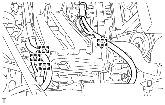
Disengage the 4 clamps and separate the wire harness from the injector cover (for bank 1).
VALVE CLEARANCE > ADJUSTMENT |
| 1. REMOVE IGNITION COIL ASSEMBLY |
| 2. REMOVE INJECTOR COVER (for Bank 1) |
|
Disengage the 4 clamps and separate the wire harness from the injector cover (for bank 1).
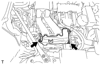 |
Remove the 2 bolts and injector cover (for bank 1).
| 3. REMOVE INJECTOR DRIVER BRACKET |
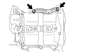 |
Remove the 2 bolts and injector driver bracket.
| 4. REMOVE CYLINDER HEAD COVER SUB-ASSEMBLY RH |
Operate the engine stand so that the bank 1 side faces upward.
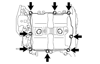 |
Remove the 8 bolts.
Using a screwdriver with its tip wrapped in protective tape, remove the cylinder head cover sub-assembly RH.
Remove the cylinder head cover gasket.
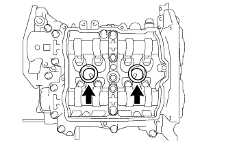 |
Remove the 2 spark plug tube gaskets.
| 5. REMOVE CYLINDER HEAD COVER SUB-ASSEMBLY LH |
Operate the engine stand so that the bank 2 side faces upward.
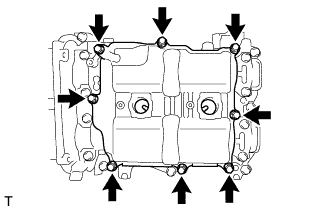 |
Remove the 8 bolts.
Using a screwdriver with its tip wrapped in protective tape, remove the cylinder head cover sub-assembly LH.
Remove the cylinder head cover gasket.
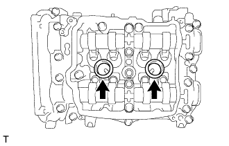 |
Remove the 2 spark plug tube gaskets.
| 6. INSPECT VALVE CLEARANCE |
Set the No. 1 cylinder to the TDC/compression.
Turn the crankshaft clockwise to align the timing mark on the crankshaft pulley with the indicator of the timing chain cover.
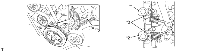
| *1 | Intake Camshaft | *2 | Exhaust Camshaft |
| *3 | No. 1 Valve Rocker Arm Sub-assembly | - | - |
| *a | Timing Mark | - | - |
At this time, check that the intake camshaft and exhaust camshaft do not depress the No. 1 cylinder intake side No. 1 valve rocker arm sub-assembly (intake valve) and exhaust side No. 1 valve rocker arm sub-assembly (exhaust valve).
Inspect the valve clearance indicated in the illustration.
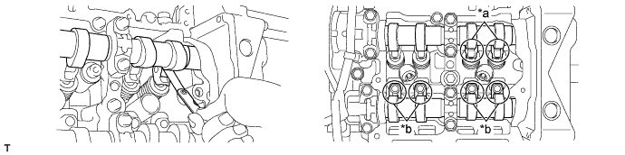
| *a | Intake Side | *b | Exhaust Side |
Measure the clearance between the surface of the cam base circle and the roller surface of the No. 1 valve rocker arm sub-assembly using a feeler gauge.
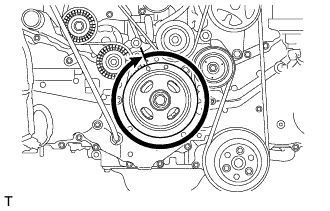 |
Turn the crank pulley by 360°.
Inspect the valve clearance indicated in the illustration.
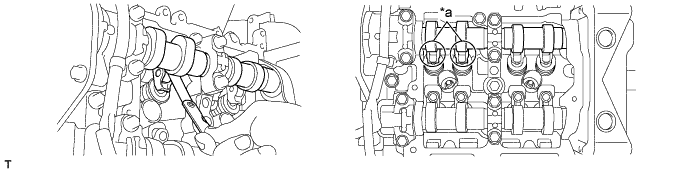
| *a | Intake Side | - | - |
Measure the clearance between the surface of the cam base circle and the roller surface of the No. 1 valve rocker arm sub-assembly using a feeler gauge.
Turn the crank pulley clockwise, set the No. 2 cylinder at TDC/compression, and then align the timing mark (notch) with 0° position of the timing chain cover.
| *1 | Intake Camshaft | *2 | Exhaust Camshaft |
| *3 | No. 1 Valve Rocker Arm Sub-assembly | - | - |
| *a | Timing Mark | - | - |
At this time, check that the intake camshaft and exhaust camshaft do not depress the No. 2 cylinder intake side No. 1 valve rocker arm sub-assembly (intake valve) and exhaust side No. 1 valve rocker arm sub-assembly (exhaust valve).
Inspect the valve clearance indicated in the illustration.
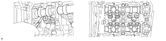
| *a | Intake Side | *b | Exhaust Side |
Measure the clearance between the surface of the cam base circle and the roller surface of the No. 1 valve rocker arm sub-assembly using a feeler gauge.
|
Turn the crank pulley by 360°.
Inspect the valve clearance indicated in the illustration.
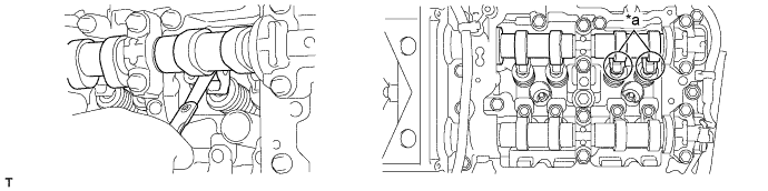
| *a | Intake Side | - | - |
Measure the clearance between the surface of the cam base circle and the roller surface of the No. 1 valve rocker arm sub-assembly using a feeler gauge.
| 7. ADJUST VALVE CLEARANCE |
Remove the camshaft housing sub-assembly.
(Click here)
Remove the No. 1 valve rocker arm sub-assemblies.
Remove the valve adjusting shims.
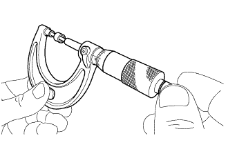 |
Using a micrometer, measure the thickness of the removed valve adjusting shims.
Calculate the thickness of the valve adjusting shim so that the valve clearance comes within the specified values.
Apply engine oil to the inner face of the valve adjusting shim, and install it to the valve.
Install the No. 1 valve rocker arm sub-assemblies.
Install the camshaft housing sub-assembly.
(Click here)
| 8. INSTALL CYLINDER HEAD COVER SUB-ASSEMBLY LH |
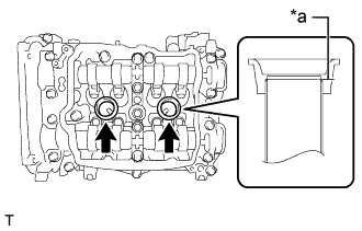 |
Apply a light layer of engine oil to 2 new spark plug tube gaskets and install them to the spark plug tubes as shown in the illustration.
| *a | Spark plug tube edge |
Install a new cylinder head cover gasket to the cylinder head cover sub-assembly LH.
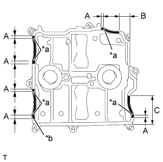 |
Using a sealer gun, apply seal packing to the mating surface of cylinder head cover sub-assembly LH as shown in the illustration.
| Area | Application Length |
| A | 10.0 mm (0.394 in.) or more |
| B | 18.8 mm (0.740 in.) or more |
| C | 63.0 mm (2.480 in.) or more |
| *a | Arch starting point |
| *b | φ2,0 to 4.0 mm (0.079 to 0.158 in.) |
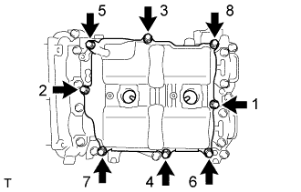 |
Tighten the 8 bolts in the order shown in the illustration and install the cylinder head cover sub-assembly LH.
| 9. INSTALL CYLINDER HEAD COVER SUB-ASSEMBLY RH |
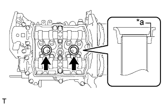 |
Apply a light layer of engine oil to 2 new spark plug tube gaskets and install them to the spark plug tubes as shown in the illustration.
| *a | Spark plug tube edge |
Install a new cylinder head cover gasket to the cylinder head cover sub-assembly RH.
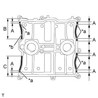 |
Using a sealer gun, apply seal packing to the mating surface of cylinder head cover sub-assembly RH as shown in the illustration.
| Area | Application Length |
| A | 10.0 mm (0.394 in.) or more |
| B | 68.0 mm (2.677 in.) or more |
| C | 70.7 mm (2.784 in.) or more |
| *a | Arch starting point |
| *b | φ2,0 to 4.0 mm (0.079 to 0.158 in.) |
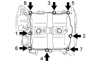 |
Tighten the 8 bolts in the order shown in the illustration and install the cylinder head cover sub-assembly RH.
| 10. INSTALL INJECTOR DRIVER BRACKET |
|
Install the injector driver bracket with the 2 bolts.
| 11. INSTALL INJECTOR COVER (for Bank 1) |
Install the injector cover (for bank 1) to the intake manifold with the 2 bolts.
Engage the 4 clamps to install the wire harness to the injector cover (for bank 1).
| 12. INSTALL IGNITION COIL ASSEMBLY |