| NG |  |
| GO TO POWER DOOR LOCK CONTROL SYSTEM (PROCEED TO PROBLEM SYMPTOMS TABLE) (Click here) |
ENTRY AND START SYSTEM (for Entry Function) > All Door Entry Lock/Unlock Functions do not Operate, but Wireless Functions Operate |
| 1.CHECK POWER DOOR LOCK OPERATION |
When the door control switch on the power window regulator master switch assembly is operated, check that the doors unlock and lock according to switch operation (Click here).
|
| ||||
| OK | |
 |
| 2.READ VALUE USING GTS (AUTO ENTRY CANCEL SW) |
Connect the GTS to the DLC3.
Turn the engine switch on (IG).
Turn the GTS on.
Enter the following menus: Body Electrical / Entry & Start / Data List.
According to the display on the GTS, read the Data List.
| Tester Display | Measurement Item/Range | Normal Condition | Diagnostic Note |
| Auto Entry Cancel SW | Entry cancel function setting / OFF or ON | Mode status displayed OFF: Entry and start system not canceled ON: Entry and start system canceled | The default setting for the entry cancel function is OFF. If the customer requests that the entry and start system functions (locking and unlocking the doors while carrying the key, etc.) be canceled, the setting can be changed through the customize function (Click here). |
| Result | Proceed to |
| Entry function cancel is OFF | A |
| Entry function cancel is ON | B |
|
| ||||
| A | |
|
| 3.CHECK WAVE ENVIRONMENT |
Move the electrical key transmitter sub-assembly as described below and perform the operation inspection (Click here).
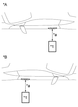 |
Bring the electrical key transmitter sub-assembly near the driver door outside handle assembly, and perform a front driver door entry lock and unlock operation check.
| *1 | Electrical Key Transmitter Sub-assembly |
| *A | for LHD |
| *B | for RHD |
| *a | Approximately 0.3 m (0.98 ft.) |
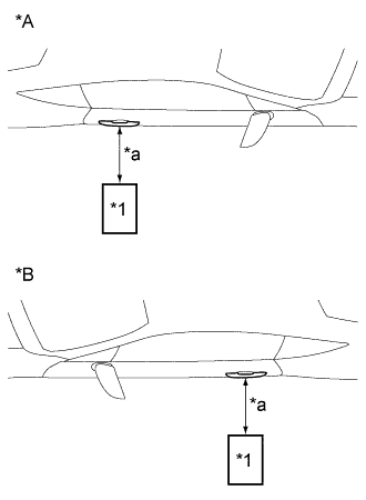 |
Bring the electrical key transmitter sub-assembly near the front passenger side door outside handle assembly, and perform a front passenger side door entry lock and unlock operation check.
| *1 | Electrical Key Transmitter Sub-assembly |
| *A | for LHD |
| *B | for RHD |
| *a | Approximately 0.3 m (0.98 ft.) |
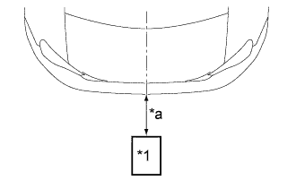 |
Bring the electrical key transmitter sub-assembly near the electrical key antenna (outside luggage), and perform an entry luggage compartment door open function check.
| *1 | Electrical Key Transmitter Sub-assembly |
| *a | Approximately 0.3 m (0.98 ft.) |
| Result | Proceed to |
| All operation checks fail | A |
| All checks are normal | B |
| Some operation checks are normal | C |
|
| ||||
|
| ||||
| A | |
|
| 4.CHECK KEY DIAGNOSTIC MODE |
Check the following antennas in the key diagnostic mode (Click here).
|
Check the electrical key antenna (for driver door):
| *1 | Electrical Key Transmitter Sub-assembly |
| *A | for LHD |
| *B | for RHD |
| *a | 0.7 to 1.0 m (2.30 to 3.28 ft.) |
|
Check the electrical key antenna (for front passenger door):
| *1 | Electrical Key Transmitter Sub-assembly |
| *A | for LHD |
| *B | for RHD |
| *a | 0.7 to 1.0 m (2.30 to 3.28 ft.) |
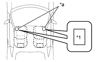 |
Check the indoor electrical key oscillator (front floor):
| *1 | Electrical Key Transmitter Sub-assembly |
| *a | Inspection point |
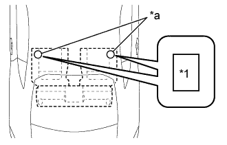 |
Check the No. 2 indoor electrical key oscillator (rear floor):
| *1 | Electrical Key Transmitter Sub-assembly |
| *a | Inspection point |
|
Check the electrical key antenna (outside luggage):
| *1 | Electrical Key Transmitter Sub-assembly |
| *a | 0.7 to 1.0 m (2.30 to 3.28 ft.) |
| Result | Proceed to |
| All diagnostic mode inspections fail | A |
| Some diagnostic mode inspections fail (door) | B |
| Some diagnostic mode inspections fail (interior) | C |
| Some diagnostic mode inspections fail (luggage compartment door) | D |
| All diagnostic mode inspections are normal | E |
|
| ||||
|
| ||||
|
| ||||
|
| ||||
| A | |
|
| 5.INSPECT ELECTRICAL KEY TRANSMITTER SUB-ASSEMBLY |
Check if there is another key available that is already registered to the vehicle.
| Result | Proceed to |
| Another registered key sub-assembly is not available | A |
| Another registered key sub-assembly is available | B |
|
| ||||
| A | |
|
| 6.REPLACE ELECTRICAL KEY TRANSMITTER SUB-ASSEMBLY |
Replace the electrical key transmitter sub-assembly.
Register the electrical key transmitter sub-assembly (Refer to the Service Bulletin).
| NEXT | |
|
| 7.CHECK ELECTRICAL KEY TRANSMITTER SUB-ASSEMBLY (OPERATION) |
Check that the entry function operates normally (Click here).
|
| ||||
| OK | ||
 | ||
| ||
