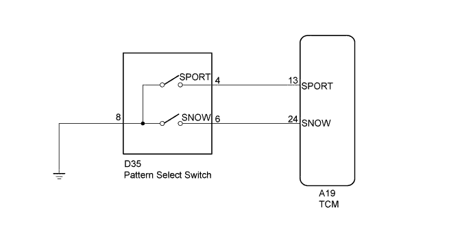
AUTOMATIC TRANSMISSION SYSTEM > Pattern Select Switch Circuit |
| 1.READ VALUE USING GTS |
Connect the GTS to the DLC3.
Turn the ignition switch to ON.
Read the value displayed on the GTS.
| Tester Display | Measurement Item/Range | Normal Condition | Diagnostic Note |
| Sport Switch Status | Pattern switch (ECT SPORT) status/ ON or OFF | Ignition switch is: ON: off ↓ Pattern switch (ECT SPORT) is: Pushed: ON ↓ Pattern switch (ECT SPORT) is: Pushed: OFF | - |
|
| ||||
| OK | |
 |
| 2.READ VALUE USING GTS |
Connect the GTS to the DLC3.
Turn the ignition switch to ON.
Read the value displayed on the GTS.
| Tester Display | Measurement Item/Range | Normal Condition | Diagnostic Note |
| Snow Switch Status | Pattern switch (ECT SNOW) status/ ON or OFF | Ignition switch is: ON: off ↓ Pattern switch (ECT SNOW) is: Pushed: ON ↓ Pattern switch (ECT SNOW) is: Pushed: OFF | - |
|
| ||||
| OK | ||
 | ||
| ||
| 3.INSPECT PATTERN SELECT SWITCH ASSEMBLY |
Perform inspection of the pattern select switch (Click here).
|
| ||||
| OK | |
|
| 4.CHECK HARNESS AND CONNECTOR (PATTERN SELECT SWITCH ASSEMBLY - TCM - BODY GROUND) |
Disconnect the TCM connector.
Disconnect the pattern select switch assembly connector.
Measure the resistance according to the value(s) in the table below.
| Tester Connection | Switch Condition | Specified Condition |
| A19-13(SPORT) - D35-4(SPORT) | Always | Below 1 Ω |
| D35-8 - Body ground | Always | Below 1 Ω |
| A19-3(SPORT) - Body ground | Always | 10 kΩ or higher |
Connect the TCM connector.
Connect the pattern select switch assembly connector.
|
| ||||
| OK | |
|
| 5.REPLACE TCM |
Replace the TCM (Click here).
| NEXT | ||
| ||
| ||
| 6.INSPECT PATTERN SELECT SWITCH ASSEMBLY |
Perform inspection of the pattern select switch (Click here).
|
| ||||
| OK | |
|
| 7.CHECK HARNESS AND CONNECTOR (PATTERN SELECT SWITCH - TCM - BODY GROUND) |
Disconnect the TCM connector.
Disconnect the pattern select switch assembly connector.
Measure the resistance according to the value(s) in the table below.
| Tester Connection | Switch Condition | Specified Condition |
| A19-24(SNOW) - D35-6 | Always | Below 1 Ω |
| D35-8 - Body ground | Always | Below 1 Ω |
| A19-24(SNOW) - Body ground | Always | 10 kΩ or higher |
Connect the TCM connector.
Connect the pattern select switch assembly connector.
|
| ||||
| OK | |
|
| 8.REPLACE TCM |
Replace the TCM (Click here).
| NEXT | ||
| ||
| ||

