Home › Suspension › FRONT SUSPENSION › FRONT STABILIZER BAR

FRONT STABILIZER BAR > INSTALLATION

for Preparation Click here


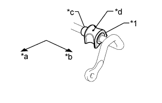
1. INSTALL FRONT NO. 1 STABILIZER BAR BUSHING (for LH Side)


    C260993E02
  1. Install the front No. 1 stabilizer bar bushing so that it is positioned closer to the outside of the vehicle than the front stabilizer bar stopper ring.

    NOTICE:
    Install the front No. 1 stabilizer bar bushing so that the arrow mark is facing towards the front of the vehicle.

    Text in Illustration 
    *1
    Front No. 1 Stabilizer Bar Bushing
    *a
    Front of the Vehicle
    *b
    Outside of the Vehicle
    *c
    Stopper Ring
    *d
    Arrow


2. INSTALL FRONT NO. 1 STABILIZER BAR BUSHING (for RH Side)

HINT:
Perform the same procedure as for the LH side.


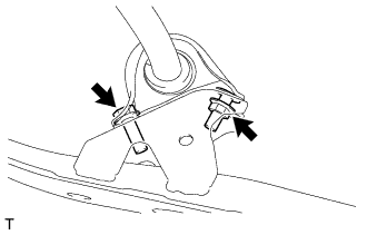
3. INSTALL FRONT NO. 2 STABILIZER BRACKET LH


    C256604
  1. Install the front No. 2 stabilizer bracket LH to the rear body mounting cushion sub-assembly with the bolt and nut.

    Torque:
    Bolt:
    75 N*m{ 765 kgf*cm , 55 ft.*lbf }
    Nut:
    25 N*m{ 255 kgf*cm , 18 ft.*lbf }


4. INSTALL FRONT NO. 2 STABILIZER BRACKET RH

HINT:
Perform the same procedure as for the LH side.


5. INSTALL REAR BODY MOUNTING CUSHION SUB-ASSEMBLY LH
  1. Install the rear body mounting cushion sub-assembly LH and front stabilizer bar with the 4 new bolts.

    Torque:
    60 N*m{ 612 kgf*cm , 44 ft.*lbf }


6. INSTALL REAR BODY MOUNTING CUSHION SUB-ASSEMBLY RH

HINT:
Perform the same procedure as for the LH side.


7. INSTALL FRONT STABILIZER LINK ASSEMBLY LH
  1. Using a hexagon wrench 6 mm, fix the stud bolt, and install the front stabilizer link assembly LH to the front stabilizer bar with a new nut.

    Torque:
    46 N*m{ 469 kgf*cm , 34 ft.*lbf }

  1. Using a hexagon wrench 6 mm, fix the stud bolt, and install the front stabilizer link assembly LH to the front shock absorber with coil spring with a new nut.

    Torque:
    46 N*m{ 469 kgf*cm , 34 ft.*lbf }


8. INSTALL FRONT STABILIZER LINK ASSEMBLY RH

HINT:
Perform the same procedure as for the LH side.


9. INSTALL REAR ENGINE UNDER COVER LH
  1. Install the rear engine under cover LH with the 3 clips.


10. INSTALL REAR ENGINE UNDER COVER RH

HINT:
Perform the same procedure as for the LH side.


11. INSTALL NO. 2 ENGINE UNDER COVER
  1. Install the 7 bolts and the No. 2 engine under cover.

    Torque:
    7.5 N*m{ 76 kgf*cm , 66 in.*lbf }


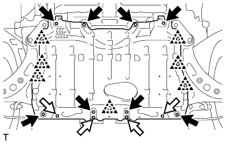
12. INSTALL NO. 1 ENGINE UNDER COVER


    A280546
  1. Install the No. 1 engine under cover with the 12 bolts and engage the 7 clips.
    V100135
    Bolt A
    V100136
    Bolt B

    Torque:
    Bolt A:
    30 N*m{ 306 kgf*cm , 22 ft.*lbf }
    Bolt B:
    7.5 N*m{ 76 kgf*cm , 66 in.*lbf }


13. INSTALL FRONT WHEEL

Torque:
120 N*m{ 1224 kgf*cm , 89 ft.*lbf }


14. STABILIZE SUSPENSION
  1. Lower the vehicle and bounce it up and down several times to stabilize the front suspension.


15. INSPECT STEERING WHEEL CENTER POINT


16. INSPECT AND ADJUST FRONT WHEEL ALIGNMENT
(Click here)


17. VSC SENSOR NEUTRAL MEMORIZATION
(Click here)


18. HEIGHT CONTROL SENSOR SIGNAL INITIALIZE (w/ HID Headlight System)
(Click here)


19. ADJUST HEADLIGHT AIMING (w/ HID Headlight System)
(Click here)