 |
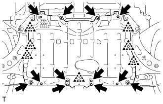
Disengage the 7 clips and remove the 12 bolts and No. 1 engine under cover.
MANUAL TRANSMISSION ASSEMBLY > REMOVAL |
| 1. DISCONNECT CABLE FROM NEGATIVE BATTERY TERMINAL |
| 2. REMOVE NO. 1 ENGINE UNDER COVER |
|
Disengage the 7 clips and remove the 12 bolts and No. 1 engine under cover.
| 3. REMOVE NO. 2 ENGINE UNDER COVER |
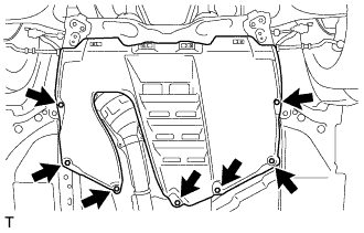 |
Remove the 7 bolts and the No. 2 engine under cover.
| 4. REMOVE REAR ENGINE UNDER COVER LH (w/ Floor Under Cover) |
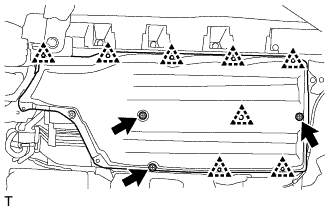 |
Remove the 3 bolts and 8 clips, then remove the rear engine under cover LH.
| 5. REMOVE REAR ENGINE UNDER COVER RH (w/ Floor Under Cover) |
| 6. DRAIN MANUAL TRANSMISSION OIL |
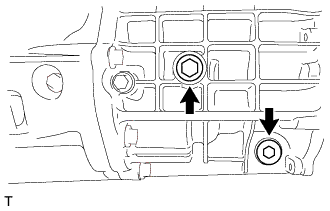 |
Remove the manual transmission filler plug and the gasket.
Remove the manual transmission drain plug and gasket, and then drain the manual transaxle oil.
Install a new gasket and the manual transmission drain plug.
| 7. REMOVE PROPELLER SHAFT WITH CENTER BEARING ASSEMBLY |
| 8. REMOVE FRONT STABILIZER BAR |
| 9. REMOVE STARTER ASSEMBLY |
| 10. SEPARATE WIRE HARNESS |
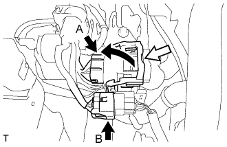 |
Release the lock of connector (A) and disconnect the connector.
Disconnect the connector (B).
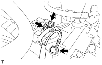 |
Disconnect the 2 connectors.
Remove the bolt and disconnect the ground cable.
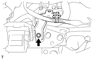 |
Disengage the wire harness clamp.
Remove the bolt and the wire harness clamp bracket.
| 11. SEPARATE CLUTCH RELEASE CYLINDER ASSEMBLY |
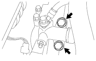 |
Remove the 2 bolts and separate the clutch release cylinder assembly.
| 12. SEPARATE MANUAL TRANSMISSION ASSEMBLY |
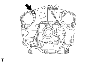 |
Remove the bolt from the manual transmission assembly.
| 13. REMOVE EXHAUST MANIFOLD |
| 14. SUPPORT ENGINE ASSEMBLY |
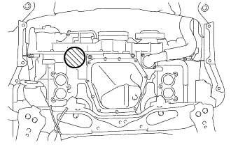 |
Support the engine assembly with an engine lifter so that it is stable, as shown in the illustration.
 | Attachment Placement Positions |
| 15. DISCONNECT FLOOR SHIFT LEVER ASSEMBLY |
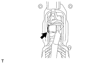 |
Turn over the shift and select lever boot.
Using a screwdriver, remove the clip and the floor shift lever assembly.
Remove the plate washer from the floor shift lever assembly.
Remove the 2 bushings and O-ring from the floor shift lever assembly.
| 16. REMOVE EXHAUST PIPE BRACKET |
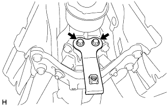 |
Remove the 2 bolts and the exhaust pipe bracket.
| 17. SUPPORT MANUAL TRANSMISSION ASSEMBLY |
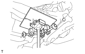 |
Support the manual transmission assembly with a transmission jack.
| 18. REMOVE REAR NO. 2 ENGINE MOUNTING INSULATOR |
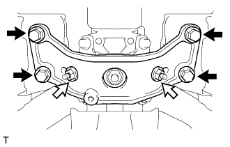 |
Remove the 4 bolts, 2 washers, 2 nuts and rear No. 2 engine mounting insulator.
 | Bolt |
 | Nut |
| 19. DISCONNECT FLOOR SHIFT CONTROL SHIFT LEVER RETAINER |
Tilt the manual transmission assembly.
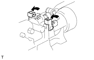 |
Pull up the locks of the shift lever pins, and remove the 2 shift lever pins.
Disconnect the floor shift control shift lever retainer.
| 20. REMOVE SHIFT AND SELECT LEVER BOOT |
Remove the shift and select lever boot from the floor shift lever assembly.
| 21. REMOVE MANUAL TRANSMISSION ASSEMBLY |
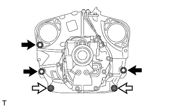 |
Remove the 3 bolts, 2 nuts and manual transmission assembly.
| Bolt |
| Nut |
| 22. REMOVE REAR NO. 1 ENGINE MOUNTING INSULATOR |
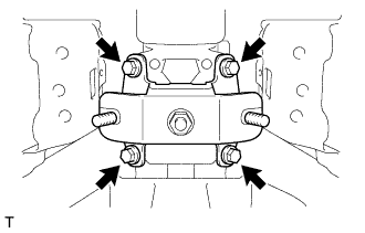 |
Remove the 4 bolts and rear No. 1 engine mounting insulator.
| 23. REMOVE FLOOR SHIFT CONTROL SHAFT |
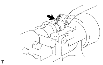 |
Using a screwdriver, remove the clip, plate washer and floor shift control shaft.
Remove the 2 collars from the control shaft.
| 24. REMOVE CONTROL SHAFT |
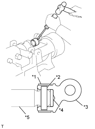 |
Using a hammer and a screwdriver, cut off the control shaft collar and remove it from the shift shaft.
Using a hexagon bar wrench, push the shaft pin up from the bottom. Attach a piece of cloth to protect the shaft pin from damage, and then remove the shaft pin using a pair of pliers.
Remove the shift lever damper from the control shaft.
| *1 | Control Shaft Collar |
| *2 | Shaft Pin |
| *3 | Control Shaft |
| *4 | Shift Lever Damper |
| *5 | Shift Shaft |