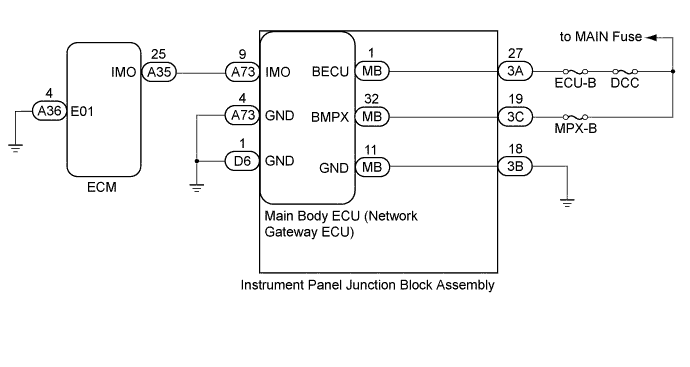
DTC B1572 Immobiliser System Communication Malfunction |
| DTC Code | DTC Detection Condition | Trouble Area |
| B1572 | When there is a problem in communication between the main body ECU (network gateway ECU) and ECM. |
|
| 1.CHECK HARNESS AND CONNECTOR (BATTERY, BODY GROUND) |
Disconnect the A73 and D6 main body ECU (network gateway ECU) connectors.
Disconnect the 3A, 3B and 3C instrument panel junction block assembly connectors.
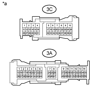 |
Measure the voltage according to the value(s) in the table below.
| Tester Connection | Condition | Specified Condition |
| 3A-27 - Body ground | Always | 11 to 14 V |
| 3C-19 - Body ground | Always | 11 to 14 V |
Measure the resistance according to the value(s) in the table below.
| Tester Connection | Condition | Specified Condition |
| 3B-18 - Body ground | Always | Below 1 Ω |
| A73-4 (GND) - Body ground | Always | Below 1 Ω |
| D6-1 (GND) - Body ground | Always | Below 1 Ω |
| *a | Component without harness connected (Instrument Panel Junction Block Assembly) |
|
| ||||
| OK | |
 |
| 2.INSPECT INSTRUMENT PANEL JUNCTION BLOCK ASSEMBLY |
Remove the instrument panel junction block assembly (Click here).
Remove the main body ECU (network gateway ECU) from the instrument panel junction block assembly.
Measure the resistance according to the value(s) in the table below.
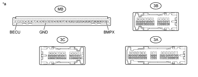
| *a | Component without harness connected (Instrument Panel Junction Block Assembly) | - | - |
| Tester Connection | Condition | Specified Condition |
| MB-1 (BECU) - 3A-27 | Always | Below 1 Ω |
| MB-32 (BMPX) - 3C-19 | Always | Below 1 Ω |
| MB-11 (GND) - 3B-18 | Always | Below 1 Ω |
|
| ||||
| OK | |
|
| 3.CHECK HARNESS AND CONNECTOR (MAIN BODY ECU (NETWORK GATEWAY ECU) - ECM) |
Disconnect the A73 main body ECU (network gateway ECU) connector.
Disconnect the A35 and A36 ECM connectors.
Measure the voltage and resistance according to the value(s) in the table below.
| Tester Connection | Condition | Specified Condition |
| A73-9 (IMO) - Body ground | Always | Below 1 V |
| A35-25 (IMO) - Body ground | Always | Below 1 V |
| Tester Connection | Condition | Specified Condition |
| A73-9 (IMO) - A35-25 (IMO) | Always | Below 1 Ω |
| A36-4 (E01) - Body ground | Always | Below 1 Ω |
| A73-9 (IMO) - Body ground | Always | 10 kΩ or higher |
|
| ||||
| OK | |
|
| 4.REPLACE ECM |
Temporarily replace the ECM with a new or known good one (Click here).
Register the ECU communication ID (Refer to Service Bulletin).
| NEXT | |
|
| 5.CHECK FOR DTC |
Turn the ignition switch to ON and wait for 5 seconds.
Check for DTCs (Click here).
|
| ||||
| OK | ||
 | ||
| ||
