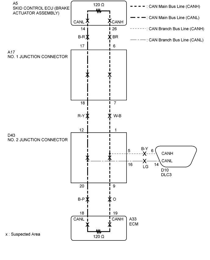
CAN COMMUNICATION SYSTEM > Open in CAN Main Bus Line (LHD Models) |
| Symptom | Trouble Area |
| Resistance between terminals 6 (CANH) and 14 (CANL) of DLC3 is 64 Ω or higher. |
|
| 1.CHECK FOR OPEN IN CAN BUS LINES (DLC3 BRANCH LINE) |
Disconnect the cable from the negative (-) battery terminal.
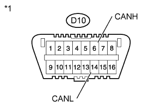 |
Measure the resistance according to the value(s) in the table below.
| Tester Connection | Condition | Specified Condition |
| D10-6 (CANH) - D10-14 (CANL) | Cable disconnected from negative (-) battery terminal | 114 to 126 Ω |
| *1 | DLC3 |
|
| ||||
| OK | |
 |
| 2.CHECK FOR OPEN IN CAN BUS LINES (ECM) |
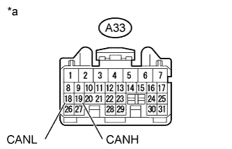 |
Disconnect the A33 ECM connector.
Measure the resistance according to the value(s) in the table below.
| Tester Connection | Condition | Specified Condition |
| A33-19 (CANH) - A33-18 (CANL) | Cable disconnected from negative (-) battery terminal | 114 to 126 Ω |
| *a | Front view of wire harness connector (to ECM) |
|
| ||||
| OK | ||
 | ||
| ||
| 3.CHECK FOR OPEN IN CAN BUS LINES (SKID CONTROL ECU (BRAKE ACTUATOR ASSEMBLY)) |
Reconnect the A33 ECM connector.
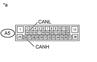 |
Disconnect the A5 skid control ECU (brake actuator assembly) connector.
Measure the resistance according to the value(s) in the table below.
| Tester Connection | Condition | Specified Condition |
| A5-26 (CANH) - A5-14 (CANL) | Cable disconnected from negative (-) battery terminal | 114 to 126 Ω |
| *a | Front view of wire harness connector (to Skid Control ECU (Brake Actuator Assembly)) |
|
| ||||
| OK | ||
| ||
| ||
| 4.CHECK FOR OPEN IN CAN BUS LINES (CAN NO. 2 J/C) |
Reconnect the A5 skid control ECU (brake actuator assembly) connector.
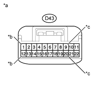 |
Disconnect the wire harness connector from the D43 CAN No. 2 junction connector.
Measure the resistance according to the value(s) in the table below.
| Tester Connection | Condition | Specified Condition | Connected to |
| D43-1 - D43-12 | Cable disconnected from negative (-) battery terminal | 114 to 126 Ω | CAN No. 1 junction connector |
| D43-9 - D43-20 | Cable disconnected from negative (-) battery terminal | 114 to 126 Ω | ECM |
| *a | Front view of wire harness connector (to CAN No. 2 Junction Connector) |
| *b | to CAN No. 1 Junction Connector |
| *c | to ECM |
| Result | Proceed to |
| OK | A |
| NG (CAN No. 1 junction connector main line) | B |
| NG (ECM main line) | C |
|
| ||||
|
| ||||
| A | ||
| ||
| ||
| 5.CHECK FOR OPEN IN CAN BUS LINES (CAN NO. 2 J/C - CAN NO. 1 J/C) |
Reconnect the wire harness connector to the D43 CAN No. 2 junction connector.
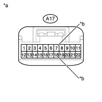 |
Disconnect the wire harness connector from the A17 CAN No. 1 junction connector.
Measure the resistance according to the value(s) in the table below.
| Tester Connection | Condition | Specified Condition |
| A17-7 - A17-18 | Cable disconnected from negative (-) battery terminal | 114 to 126 Ω |
| *a | Front view of wire harness connector (to CAN No. 1 Junction Connector) |
| *b | to CAN No. 2 Junction Connector |
|
| ||||
| OK | |
|
| 6.CHECK FOR OPEN IN CAN BUS LINES (CAN NO. 1 J/C - SKID CONTROL ECU (BRAKE ACTUATOR ASSEMBLY)) |
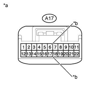 |
Measure the resistance according to the value(s) in the table below.
| Tester Connection | Condition | Specified Condition |
| A17-6 - A17-17 | Cable disconnected from negative (-) battery terminal | 114 to 126 Ω |
| *a | Front view of wire harness connector (to CAN No. 1 Junction Connector) |
| *b | to Skid Control ECU (Brake Actuator Assembly) |
|
| ||||
| OK | ||
| ||
| ||

