CLUTCH CLUTCH PEDAL(for LHD) INSTALLATION
PROCEDURE

 31321
1.INSTALL CLUTCH PEDAL PAD
Install the clutch pedal pad to the clutch pedal sub-assembly.
31301B
2.INSTALL NO. 1 CLUTCH PEDAL CUSHION
Install the No. 1 clutch pedal cushion to the clutch pedal sub-assembly.
31322
3.INSTALL CLUTCH PEDAL STOPPER
Install the clutch pedal stopper to the clutch pedal support sub-assembly.
31301
4.INSTALL CLUTCH PEDAL SUB-ASSEMBLY
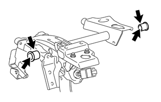
Apply MP grease to the 2 clutch pedal bushes.

|
MP grease |
Install the clutch pedal sub-assembly and 2 clutch pedal bushes to the clutch pedal support sub-assembly.
Using a pin punch (3 mm (0.118 in.)) and a hammer, align the clutch pedal lever sub-assembly hole and the clutch pedal sub-assembly hole, and insert the straight pin from above.
31301A
5.INSTALL CLUTCH PEDAL SPRING
Install the 2 bushes to the clutch pedal sub-assembly and clutch pedal support sub-assembly.
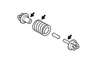
Apply MP grease to the assist rod A, assist rod B and clutch pedal spring.
|
|
MP grease |
Install the assist rod A, assist rod B, clutch pedal spring and assist bush to the clutch pedal sub-assembly and the clutch pedal support sub-assembly.
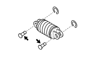
Apply MP grease to the 2 clevis pins.
|
|
MP grease |
Install the 2 clevis pins and 2 E-rings.
- HINT:
-
Install the clevis pin from the left side of the vehicle.
88280A
6.INSTALL CLUTCH SWITCH ASSEMBLY
Install the clutch switch assembly to the clutch pedal support sub-assembly with the nut.
- Torque:
- 8.0 N*m (82 kgf*cm, 71 in.*lbf)
84520
7.INSTALL CLUTCH START SWITCH ASSEMBLY
55107A
8.INSTALL CLUTCH PEDAL SUPPORT SUB-ASSEMBLY
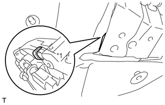
Insert the hook on the clutch pedal support sub-assembly into the vehicle panel.
| *1 | Hook |
Install the clutch pedal support sub-assembly to the vehicle with the 4 nuts and 3 bolts.
- Torque:
- 18 N*m (184 kgf*cm, 13 ft.*lbf)
Install the clutch master cylinder assembly with the 2 nuts.
- Torque:
- 18 N*m (184 kgf*cm, 13 ft.*lbf)
Apply MP grease to the new clevis pin.
Install the clutch master cylinder push rod clevis to the clutch pedal lever sub-assembly with the clevis pin and a clip.
- HINT:
-
Install the clevis pin from the left side of the vehicle.
Apply MP grease to the push rod pin.
Install the brake master cylinder push rod clevis with the push rod pin and a clip.
- HINT:
-
Install the push rod pin from the left side of the vehicle.
Connect the connector and engage the wire harness clamp.
Connect the 3 connectors.
9.INSTALL STEERING INTERMEDIATE SHAFT ASSEMBLY
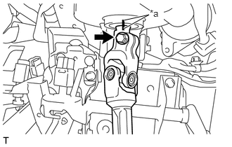
Install the steering intermediate shaft assembly to the steering column assembly.
| *a | Matchmark |
- NOTICE:
-
Align the matchmarks on the steering intermediate shaft assembly and the steering column assembly.
Install the bolt.
- Torque:
- 35 N*m (357 kgf*cm, 26 ft.*lbf)
10.INSPECT AND ADJUST CLUTCH PEDAL
88280A
11.INSPECT CLUTCH SWITCH ASSEMBLY
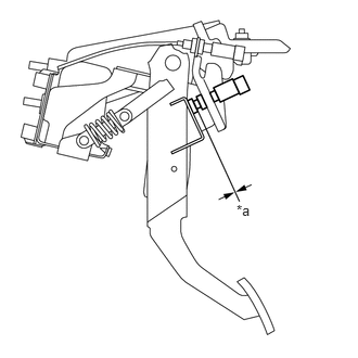
Without depressing the clutch pedal sub-assembly, check that there is no clearance between the clutch switch shaft and the clutch pedal stopper.
| *a | No Clearance |
12.INSTALL STEERING CONTROL ECU
13.INSPECT CLUTCH START SYSTEM