Home › Suspension › TIRE PRESSURE MONITORING › TIRE PRESSURE WARNING SYSTEM › from 2014.05
RM2090E _53 Suspension _060682 TIRE PRESSURE MONITORING _0297611 TIRE PRESSURE WARNING SYSTEM J

TIRE PRESSURE MONITORING  TIRE PRESSURE WARNING SYSTEM  TC and CG Terminal Circuit  


DESCRIPTION

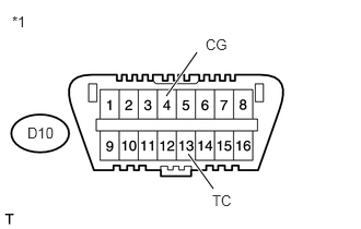
DTC output mode is set by connecting terminals 13 (TC) and 4 (CG) of the DLC3. The DTCs are indicated by the blinking of the tire pressure warning light.

WIRING DIAGRAM
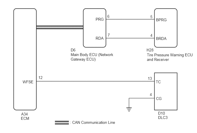
C305305E03
2.573,1.896 4.271,2.26 1.698,0.365 10 false Main Body ECU (Network Gateway ECU) 5.75,4.177 6.26,4.542 0.51,0.365 10 false DLC3 5.75,4.021 6.198,4.198 0.448,0.177 10 false D10 0.76,4.208 1.271,4.573 0.51,0.365 10 false ECM 0.771,4.052 1.25,4.219 0.479,0.167 10 false A34 5.469,0.521 5.635,0.719 0.167,0.198 10 false 5 3.906,0.51 4.146,0.708 0.24,0.198 10 false 6 3.917,1.188 4.156,1.385 0.24,0.198 10 false 7 5.469,1.198 5.635,1.396 0.167,0.198 10 false 4 5.677,0.635 6.302,0.906 0.625,0.271 10 false BPRG 5.677,1.313 6.302,1.583 0.625,0.271 10 false BRDA 3.479,0.615 4.104,0.885 0.625,0.271 10 false PRG 3.479,1.302 4.104,1.573 0.625,0.271 10 false RDA 2.573,1.729 3.063,1.896 0.49,0.167 10 false D6 5.333,1.729 5.823,1.896 0.49,0.167 10 false H28 5.667,2.885 6.292,3.156 0.625,0.271 10 false TC 5.375,2.76 5.635,2.969 0.26,0.208 10 false 13 1.396,2.729 1.635,2.948 0.24,0.219 10 false 12 5.448,3.344 5.635,3.552 0.188,0.208 10 false 4 0.823,2.885 1.375,3.073 0.552,0.188 10 false WFSE 5.677,3.49 6.302,3.76 0.625,0.271 10 false CG 5.344,1.906 7.042,2.25 1.698,0.344 10 false Tire Pressure Warning ECU and Receiver 2.552,4.354 4.344,4.719 1.792,0.365 10 false : CAN Communication Line

PROCEDURE

1.CHECK CAN COMMUNICATION SYSTEM
a.

Check if a CAN communication system DTC is output (See page Power Source / Network>NETWORKING>CAN COMMUNICATION SYSTEM>DIAGNOSIS SYSTEM).

Result
Result Proceed to
DTCs are not output A
DTCs are output B


A

2.CHECK DTC (C2179/79)

B

2.CHECK DTC (C2179/79)
a.

Check if DTC C2179/79 is output (See page Suspension>TIRE PRESSURE MONITORING>TIRE PRESSURE WARNING SYSTEM>DTC CHECK / CLEAR).

Result:
Result Proceed to
DTC C2179/79 is not output. A
DTC C2179/79 is output. B


A

3.CHECK HARNESS AND CONNECTOR (TC of DLC3 - ECM)

B

3.CHECK HARNESS AND CONNECTOR (TC of DLC3 - ECM)
a.

Disconnect the A34 ECM connector.


b.

Measure the resistance according to the value(s) in the table below.

Standard Resistance:
Tester Connection Condition Specified Condition
D10-13 (TC) - A34-12 (WFSE) Always Below 1 Ω
D10-13 (TC) - Body ground Always 10 kΩ or higher


OK

4.CHECK HARNESS AND CONNECTOR (CG of DLC3 - BODY GROUND)

NG

REPAIR OR REPLACE HARNESS OR CONNECTOR

4.CHECK HARNESS AND CONNECTOR (CG of DLC3 - BODY GROUND)
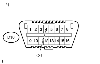
a.
U190318E02
1.573,1.042 1.365,1.781 true 0.198,0.083 0.875,0.365 0.677,0.281 10 false *1 1.25,1.813 1.604,1.99 0.354,0.177 10 false CG 0.25,1.188 0.615,1.344 0.365,0.156 10 false D10

Measure the resistance according to the value(s) in the table below.

Standard Resistance:
Tester Connection Condition Specified Condition
D10-4 (CG) - Body ground Always Below 1 Ω


Text in Illustration
*1 Front view of DLC3


OK

5.INSPECT DLC3 (TC VOLTAGE)

NG

REPAIR OR REPLACE HARNESS OR CONNECTOR

5.INSPECT DLC3 (TC VOLTAGE)
a.
U190319E02
1.792,1.469 2.031,1.802 true 1.583,0.917 1.875,0.5 true 0.115,0.125 0.792,0.406 0.677,0.281 10 false *1 2.021,1.833 2.542,2.01 0.521,0.177 10 false TC 1.958,0.344 2.479,0.521 0.521,0.177 10 false CG 0.26,1.188 0.552,1.365 0.292,0.177 10 false D10

Connect the A34 ECM connector.


b.

Measure the voltage according to the value(s) in the table below.

Standard Voltage:
Tester Connection Switch Condition Specified Condition
D10-13 (TC) - D10-4 (CG) Ignition switch ON 11 to 14 V


Text in Illustration
*1 Front view of DLC3


OK

PROCEED TO NEXT SUSPECTED AREA SHOWN IN PROBLEM SYMPTOMS TABLE

NG