POWER DISTRIBUTION ELECTRIC POWER CONTROL SYSTEM B1012 Battery Power Supply Back Up Circuit
DESCRIPTION
B1012 is stored when a malfunction is detected in the BECU circuit.
- HINT:
-
In some cases, none of the functions of the main body ECU (network gateway ECU) may function when B1011 is stored together with B1012.
| DTC No. | DTC Detection Condition | Trouble Area |
|---|---|---|
| B1012 | When BECU voltage is 8.3 V or less, or 16.7 V or more (BECU circuit malfunction) | ·
Main body ECU (network gateway ECU) ·
Instrument panel junction block assembly ·
Harness or connector |
WIRING DIAGRAM
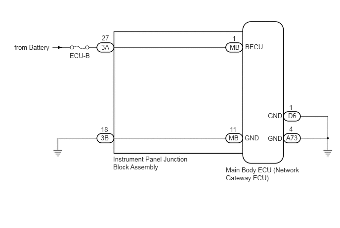
CAUTION / NOTICE / HINT
- NOTICE:
-
Inspect the fuses for circuits related to this system before performing the following inspection procedure.
PROCEDURE
Clear the DTCs (See page Power Source / Network>POWER DISTRIBUTION>ELECTRIC POWER CONTROL SYSTEM>DTC CHECK / CLEAR).
NEXT
Check for DTCs (See page Power Source / Network>POWER DISTRIBUTION>ELECTRIC POWER CONTROL SYSTEM>DTC CHECK / CLEAR).
| Result | Proceed to |
|---|---|
| DTC B1012 is output | A |
| DTC is not output | B |
A
B
(See pageGeneral>INTRODUCTION>HOW TO TROUBLESHOOT ECU CONTROLLED SYSTEMS>HOW TO PROCEED WITH TROUBLESHOOTING)
Disconnect the 3A instrument panel junction block assembly connector.
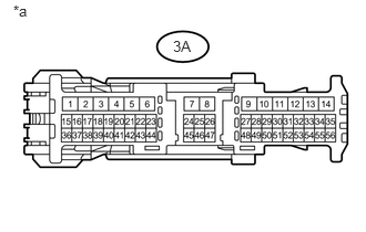
Measure the voltage according to the value(s) in the table below.
- Standard Voltage:
Tester Connection Condition Specified Condition 3A-27 - Body ground Always 11 to 14 V
| *a | Front view of wire harness connector
(to Instrument Panel Junction Block Assembly) |
OK
NG
OK
NG
Remove the instrument panel junction block assembly (See page Power Source / Network>POWER DISTRIBUTION>MAIN BODY ECU>REMOVAL).
Remove the main body ECU (network gateway ECU) from the instrument panel junction block assembly.
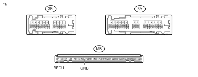
| *a | Component without harness connected
(Instrument Panel Junction Block Assembly) |
- | - |
Measure the resistance according to the value(s) in the table below.
- Standard Resistance:
Tester Connection Condition Specified Condition 3A-27 - MB-1 (BECU) Always Below 1 Ω 3B-18 - MB-11 (GND) Always Below 1 Ω
OK
NG