NETWORKING LIN COMMUNICATION SYSTEM B2321 Lost Communication with Driver Door Power Window ECU B2325 LIN Communication Bus Malfunction
DESCRIPTION
B2321 is stored when the communication between the power window regulator master switch assembly and the main body ECU (network gateway computer) stops for 10 seconds or more.
The main body ECU (network gateway computer) monitors communication between all the ECUs connected to the door LIN bus. When the main body ECU (network gateway computer) detects errors in communication with all the ECUs connected to the door LIN bus at 2.6-second intervals and 3 times in a row, DTC B2325 will be stored.
| DTC No. | DTC Detection Condition | Trouble Area |
|---|---|---|
| B2321 | Lost communication between the multiplex network master switch assembly and the main body ECU (network gateway computer). | ·
Power window regulator master switch assembly ·
Main body ECU (network gateway ECU) ·
Harness or connector |
| B2325 | The main body ECU (network gateway computer) detects errors in door LIN bus communication lines at 2.6-second intervals and 3 times in a row. | ·
Power window regulator master switch assembly ·
Main body ECU (network gateway ECU) ·
Harness or connector |
WIRING DIAGRAM
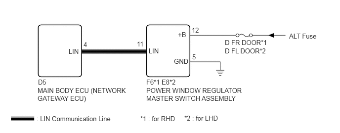
CAUTION / NOTICE / HINT
- NOTICE:
- ·
When using the GTS with the ignition switch off to troubleshoot:
Connect the GTS to the vehicle and turn a courtesy light switch on and off at 1.5 second intervals until communication between the GTS and vehicle begins.
·Inspect the fuses for circuits related to this system before performing the following inspection procedure.
- HINT:
-
When communication between the power window regulator master switch assembly and the main body ECU (network gateway ECU) stops, DTC B2325 is also stored.
PROCEDURE
Clear the DTCs (See page Power Source / Network>NETWORKING>LIN COMMUNICATION SYSTEM>DTC CHECK / CLEAR).
NEXT
Check for DTCs (See page Power Source / Network>NETWORKING>LIN COMMUNICATION SYSTEM>DTC CHECK / CLEAR).
| Result | Proceed to |
|---|---|
| DTC B2321 or B2325 is output | A |
| DTC B2321 or B235 is not output | B |
A
B
(See pageGeneral>INTRODUCTION>HOW TO TROUBLESHOOT ECU CONTROLLED SYSTEMS>HOW TO PROCEED WITH TROUBLESHOOTING)
Disconnect the D5 main body ECU (network gateway ECU) connector.
Disconnect the F6*1 or E8*2 power window regulator master switch assembly connector.
Measure the resistance according to the value(s) in the table below.
- Standard Resistance (Check for Open):
Tester Connection Condition Specified Condition D5-4 (LIN) - F6-11 (LIN)*1 Always Below 1 Ω D5-4 (LIN) - E8-11 (LIN)*2
- Standard Resistance (Check for Short):
Tester Connection Condition Specified Condition D5-4 (LIN) or F6-11 (LIN) - Body ground*1 Always 10 kΩ or higher D5-4 (LIN) or E8-11 (LIN) - Body ground*2
*1 : for RHD
*2 : for LHD
OK
NG
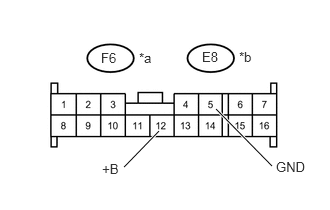
Measure the resistance according to the value(s) in the table below.
- Standard Resistance:
Tester Connection Condition Specified Condition F6-5 (GND) - Body ground*1 Always Below 1 Ω E8-5 (GND) - Body ground*2
Measure the voltage according to the value(s) in the table below.
- Standard Voltage:
Tester Connection Condition Specified Condition F6-12 (+B) - Body ground*1 Always 11 to 14 V E8-12 (+B) - Body ground*2
| *a | Front view of wire harness connector
(to Power Window Regulator Master Switch Assembly (for RHD))*1 |
| *b | Front view of wire harness connector
(to Power Window Regulator Master Switch Assembly (for LHD))*2 |
*1 : for RHD
*2 : for LHD
OK
NG
Temporarily replace the power window regulator master switch assembly with a new or normally functioning one (See page Vehicle Exterior>WINDOW / GLASS>POWER WINDOW MASTER SWITCH>REMOVAL).
NEXT
Clear the DTCs (See page Power Source / Network>NETWORKING>LIN COMMUNICATION SYSTEM>DTC CHECK / CLEAR).
NEXT
Check for DTCs (See page Power Source / Network>NETWORKING>LIN COMMUNICATION SYSTEM>DTC CHECK / CLEAR).
- OK:
DTC B2321 or B2325 is not output.
OK
NG