INTERIOR PANELS / TRIM UPPER INSTRUMENT PANEL INSTALLATION
PROCEDURE

 55302C
1.INSTALL INSTRUMENT PANEL SUB-ASSEMBLY
Install the instrument panel sub-assembly with the 7 screws and 2 bolts.
73960A
2.INSTALL INSTRUMENT PANEL PASSENGER AIRBAG ASSEMBLY
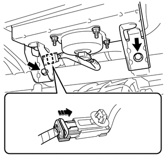
Install the instrument panel passenger airbag assembly with the 2 bolts.
- Torque:
- 7.5 N*m (76 kgf*cm, 66 in.*lbf)
Connect the passenger airbag connector.
Engage the clamp.
89120A
3.INSTALL AUTOMATIC LIGHT CONTROL SENSOR (w/ Automatic Light Control System)
55461A
4.INSTALL INSTRUMENT PANEL ORNAMENT
Engage the 3 claws and 3 clips and install the instrument panel ornament.
83100
5.INSTALL COMBINATION METER ASSEMBLY
62212
6.INSTALL FRONT PILLAR GARNISH LH
Remove the protective cover (w/curtain shield airbag).
Make sure that the front pillar garnish clip is not damaged.
- NOTICE:
-
If there is any damage, replace the front pillar garnish clip with a new one.
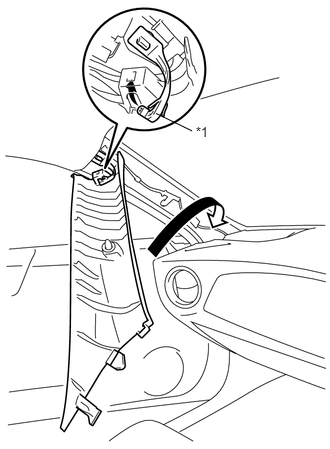
Hook the tip of the front pillar garnish clip on the front pillar garnish LH as shown in the illustration.
| *1 | Front Pillar Garnish Clip |
Turn the front pillar garnish LH in the direction of the arrow.
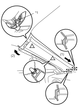
Insert the 2 guides in the direction of the arrow (1).
Engage the 2 clips and the front pillar garnish clip in the direction of the arrow, and install the front pillar garnish LH.
| *1 | Front Pillar Garnish Clip |
62211
7.INSTALL FRONT PILLAR GARNISH RH
- HINT:
-
Use the same procedure as for the LH side.
86160P
8.INSTALL FRONT NO. 2 SPEAKER ASSEMBLY (for 6 Speakers)
55409F
9.INSTALL NO. 2 INSTRUMENT PANEL SPEAKER PANEL SUB-ASSEMBLY
Connect connector.
Engage the 6 claws to install the No. 2 instrument panel speaker panel sub-assembly.
86160P
10.INSTALL FRONT NO. 2 SPEAKER ASSEMBLY (for 6 Speakers)
55408F
11.INSTALL NO. 1 INSTRUMENT PANEL SPEAKER PANEL SUB-ASSEMBLY
- HINT:
-
Use the same procedure as for the LH side.
55303B
12.INSTALL LOWER INSTRUMENT PANEL SUB-ASSEMBLY
13.CONNECT CABLE TO NEGATIVE BATTERY TERMINAL
- Torque:
- 6.0 N*m (61 kgf*cm, 53 in.*lbf)
14.CHECK SRS WARNING LIGHT