3SZ-VE ENGINE CONTROL SFI SYSTEM(w/ Rear Heated Oxygen Sensor) P0420 Catalyst System Efficiency Below Threshold (Bank 1)
DESCRIPTION
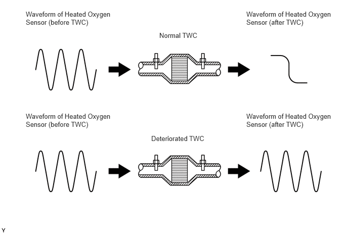
The ECM uses the heated oxygen sensors mounted in front of and behind the Three-Way Catalytic Converter (TWC) to monitor its efficiency. The front heated oxygen sensor (sensor 1) sends pre-TWC air-fuel ratio information to the ECM, and the rear heated oxygen sensor (sensor 2) sends post-TWC air-fuel ratio information to the ECM. The ECM compares the 2 signals to assess the efficiency of the TWC and the TWC's ability to store oxygen. During normal operation, the TWC stores and releases oxygen as needed. This capacity to store oxygen reduces the variation in the post-TWC exhaust stream as shown below.
If the TWC is functioning normally, the waveform of sensor 2 slowly fluctuates between RICH and LEAN.
As the TWC efficiency deteriorates, its ability to store oxygen reduces and the sensor output becomes more variable.
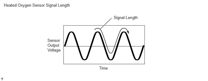
When the TWC monitor runs, the ECM measures the signal lengths of both sensors 1 and 2, and then calculates the ratio of the signal lengths (TWC deterioration level). If the TWC deterioration level exceeds the threshold, the ECM interprets this as a TWC malfunction. The ECM illuminates the MIL and sets the DTC.
| DTC No. | Detection Item | DTC Detection Condition | Trouble Area | MIL | Memory |
|---|---|---|---|---|---|
| P0420 | Catalyst System Efficiency Below Threshold (Bank 1) | The ratio of the signal lengths (the signal length of oxygen sensor 2 / the signal length of oxygen sensor 1) smaller than standard value
(2 trip detection logic) |
·
Heated oxygen sensor (sensor 1) ·
Heated oxygen sensor (sensor 2) ·
Gas leakage from exhaust system ·
Exhaust manifold (with TWC) |
Comes on | DTC stored |
CATALYST LOCATION
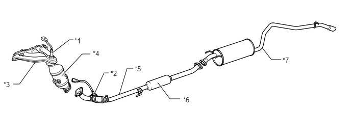
| *1 | Heated Oxygen Sensor (Sensor 1) | *2 | Heated Oxygen Sensor (Sensor 2) |
| *3 | Exhaust Manifold | *4 | TWC: Front Catalyst |
| *5 | Front Exhaust Pipe Assembly | *6 | TWC: Rear Catalyst |
| *7 | Exhaust Tail Pipe Assembly | - | - |
WIRING DIAGRAM
Refer to DTC P0130 (See page Engine / Hybrid System>3SZ-VE ENGINE CONTROL>SFI SYSTEM(w/ Rear Heated Oxygen Sensor)>P0130).
CAUTION / NOTICE / HINT
- HINT:
- ·
Read freeze frame data using the intelligent tester or Techstream. Freeze frame data records the engine conditions when a malfunction is detected. When troubleshooting, freeze frame data can help determine if the vehicle was running or stopped, if the engine was warmed up or not, if the air-fuel ratio was LEAN or RICH, and other data from the time the malfunction occurred.
·If problems could not be localized in DTC P0420 troubleshooting process, the air-fuel ratio may be too lean or too rich. In that case, carry out inspections according to the inspection procedures of DTC P0171 and DTC P0172 (See page Engine / Hybrid System>3SZ-VE ENGINE CONTROL>SFI SYSTEM(w/ Rear Heated Oxygen Sensor)>P0171).
PROCEDURE
Connect the intelligent tester or Techstream to the DLC3.
Turn the ignition switch to ON.
Turn the intelligent tester or Techstream on.
Enter the following menus: Powertrain / Engine/ Trouble Codes.
- Powertrain > Engine > Trouble Codes
- 50001 206
Read DTCs.
- Result:
Result Proceed to P0420 A P0420 and other DTCs B
- HINT:
-
If any DTCs other than P0420 are output, troubleshoot those DTCs first.
A
B
Inspect the heated oxygen sensor (sensor 1).
Inspect the heated oxygen sensor (sensor 2).
- Result:
Result Proceed to NG A NG (Heated oxygen sensor (sensor 1)) B NG (Heated oxygen sensor (sensor 2)) C
A
B
C
Inspect for exhaust gas leaks from the exhaust manifold sub-assembly and exhaust pipes.
- OK:
No gas leakage.
- Result:
Proceed to OK NG
OK
NG