3SZ-VE ENGINE CONTROL SFI SYSTEM(w/ Rear Heated Oxygen Sensor) P0130 Oxygen Sensor Circuit Malfunction (Bank 1 Sensor 1)
DESCRIPTION
- HINT:
-
Heated oxygen sensor refers to the sensor mounted in front of the Three-Way Catalytic Converter (TWC) and located near the engine assembly.
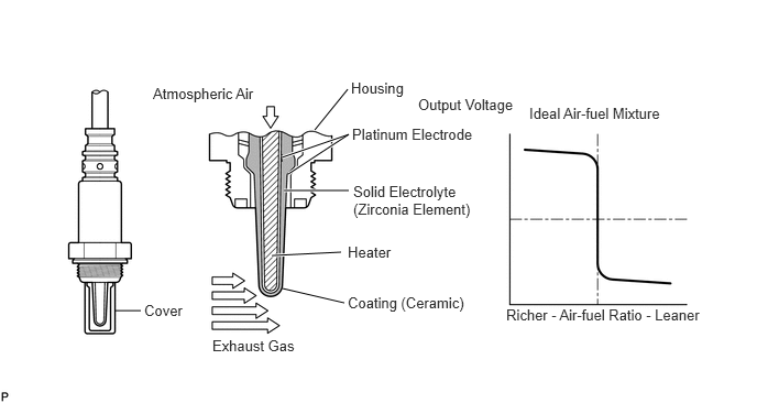
In order to obtain a high purification rate of the carbon monoxide (CO), hydrocarbon (HC) and nitrogen oxide (NOx) components in the exhaust gas, a TWC is used. For the most efficient use of the TWC, the air-fuel ratio must be precisely controlled so that it is always close to the stoichiometric air-fuel level. For the purpose of helping the ECM to deliver accurate air-fuel ratio control, a Heated Oxygen (HO2) sensor is used. The HO2 sensor is located in front of the TWC, and detects the oxygen concentration in the exhaust gas.
Since the sensor is integrated with the heater that heats the sensing portion, it is possible to detect the oxygen concentration even when the intake air volume is low (the exhaust gas temperature is low). When the air-fuel ratio becomes lean, the oxygen concentration in the exhaust gas is rich. The HO2 sensor indicates to the ECM that the pre-TWC air-fuel ratio is lean (low voltage, i.e. less than 0.45 V).
Conversely, when the air-fuel ratio is richer than the stoichiometric air-fuel level, the oxygen concentration in the exhaust gas becomes lean. The HO2 sensor indicates to the ECM that the pre-TWC air-fuel ratio is rich (high voltage, i.e. more than 0.45 V). The HO2 sensor has the property of changing its output voltage drastically when the air-fuel ratio is close to the stoichiometric level.
The ECM uses the supplementary information from the HO2 sensor to determine whether the air-fuel ratio in front of the TWC is rich or lean, and adjusts the fuel injection time accordingly. Thus, if the HO2 sensor is working improperly due to internal malfunctions, the ECM is unable to compensate for deviations in the primary air-fuel ratio control.
| DTC No. | Detection Item | DTC Detection Condition | Trouble Area | MIL | Memory |
|---|---|---|---|---|---|
| P0130 | Oxygen Sensor Circuit Malfunction (Bank 1 Sensor 1) | Following conditions (a) and (b) met after engine warmed up (2 trip detection logic):
(a) Vehicle driven under specified vehicle load or more for 20 seconds or more (b) Output voltage of heated oxygen sensor remains at less than 0.08 V or no rich signal input to ECM |
·
Open or short in heated oxygen sensor (sensor 1) circuit ·
Heated oxygen sensor (sensor 1) ·
Heated oxygen sensor heater (sensor 1) ·
Ventilation hose ·
Fuel pressure ·
Fuel injector assembly ·
Ignition system ·
ECM |
Comes on | DTC stored |
WIRING DIAGRAM
CONFIRMATION DRIVING PATTERN
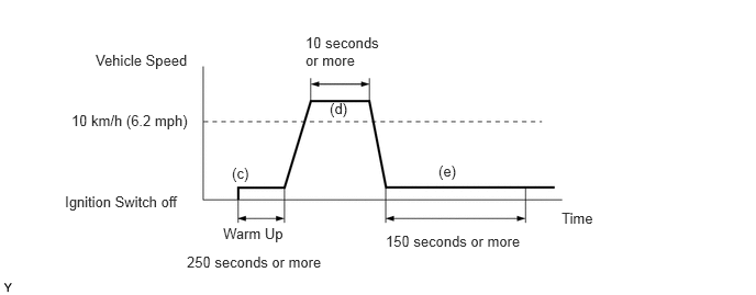
(a) Connect the intelligent tester or Techstream to the DLC3.
(b) Turn the ignition switch to ON and turn the intelligent tester or Techstream on. Then clear the DTCs (See page Engine / Hybrid System>3SZ-VE ENGINE CONTROL>SFI SYSTEM(w/ Rear Heated Oxygen Sensor)>DTC CHECK / CLEAR).
(c) Start the engine and warm it up for 250 seconds or more.
(d) Drive the vehicle at 10 km/h (6.2 mph) or more for 10 seconds or more.
(e) Stop the vehicle and allow the engine to idle for 150 seconds or more.
(f) Turn the ignition switch off, then repeat the steps (c) to (e) again.
(g) Read DTCs.
- HINT:
-
If a malfunction exists, the MIL will illuminate during step (e) because this DTC adopts 2 trip detection logic.
- NOTICE:
-
If the conditions in this test are not strictly followed, malfunctions may not be detected.
- Powertrain > Engine > Clear DTCs
- 50002 206
- Powertrain > Engine > Trouble Codes
- 50001 206
CAUTION / NOTICE / HINT
- HINT:
- ·
If other DTCs relating to different systems that have terminal E2 as the ground terminal are output simultaneously, terminal E2 may have an open circuit.
·Read freeze frame data using the intelligent tester or Techstream. Freeze frame data record the engine condition when malfunctions are detected. When troubleshooting, freeze frame data can help determine if the vehicle was moving or stationary, if the engine was warmed up or not, if the air-fuel ratio was lean or rich, and other data, from the time the malfunction occurred.
PROCEDURE
Connect the intelligent tester or Techstream to the DLC3.
Turn the ignition switch to ON.
Turn the intelligent tester or Techstream on.
Enter the following menus: Powertrain / Engine / Trouble Codes.
- Powertrain > Engine > Trouble Codes
- 50001 206
Read DTCs.
- Result:
Result Proceed to P0130 A P0130 and other DTCs B
- HINT:
-
If any DTCs other than P0130 are output, troubleshoot those DTCs first.
A
B
Connect the intelligent tester or Techstream to the DLC3.
Turn the ignition switch to ON.
Turn the intelligent tester or Techstream on.
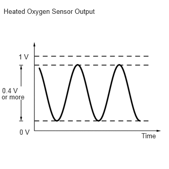
Enter the following menus: Powertrain / Engine / Data List / O2S B1 S1.
- Powertrain > Engine > Data List
-
Tester Display O2S B1 S1 - 50003 206 37
Warm up the engine.
Allow the engine to run for 90 seconds at 2500 rpm.
Read the output voltage of the heated oxygen sensor when the engine is idling and revving up.
- OK:
Fluctuates with an amplitude of 0.4 V or more.
- Result:
Result Proceed to NG A OK B
A
B
Inspect the heated oxygen sensor (sensor 1).
- Result:
Proceed to OK NG
OK
NG
Check for ventilation hose connections.
- OK:
Ventilation hose is connected correctly and is not damaged.
- Result:
Proceed to OK NG
OK
NG
Disconnect the heated oxygen sensor connector.
Disconnect the ECM connector.
Measure the resistance according to the value(s) in the table below.
- Standard Resistance (Check for Open):
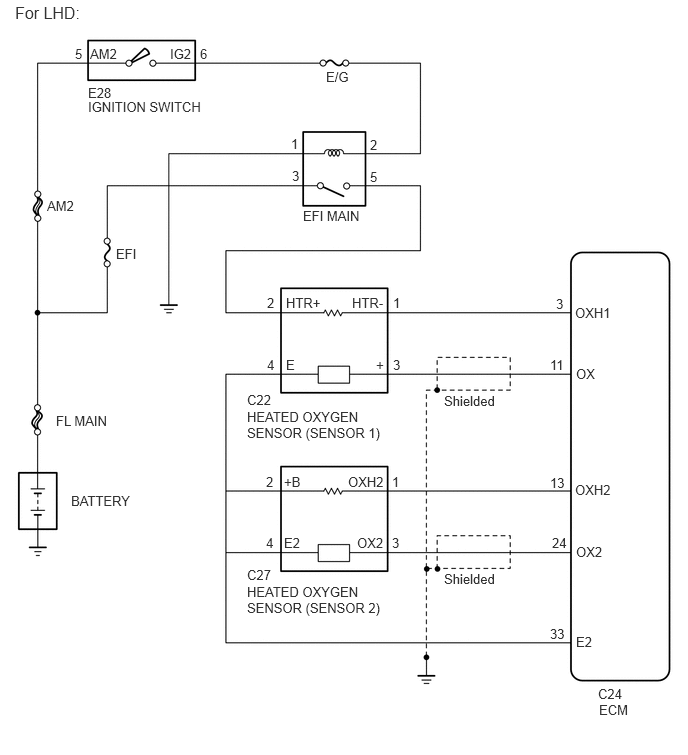
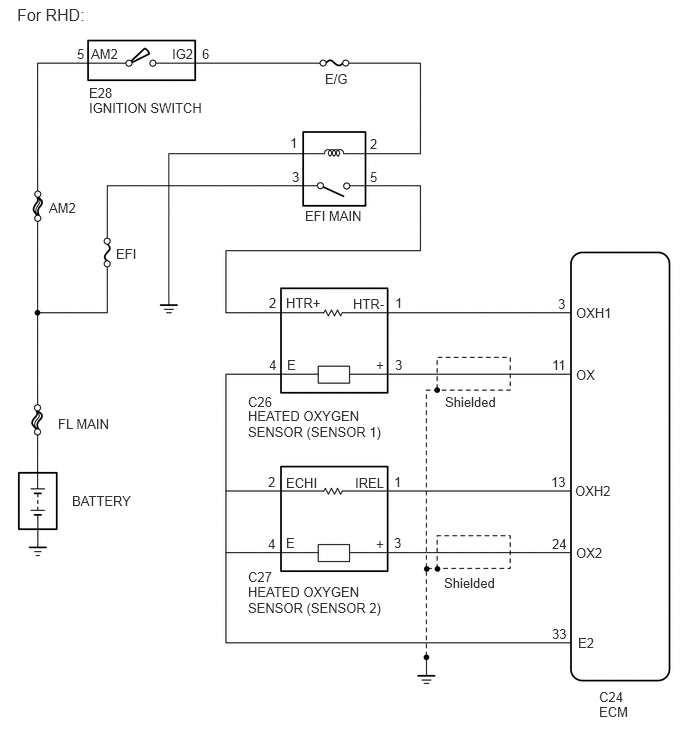
For LHD Tester Connections Condition Specified Conditions C22-3 (+) - C24-11 (OX) Always Below 1 Ω C22-1 (HTR-) - C24-3 (OXH1) Always Below 1 Ω C22-4 (E) - C24-33 (E2) Always Below 1 Ω
For RHD Tester Connections Condition Specified Conditions C26-3 (+) - C24-11 (OX) Always Below 1 Ω C26-1 (HTR-) - C24-3 (OXH1) Always Below 1 Ω C26-4 (E) - C24-33 (E2) Always Below 1 Ω
- Standard Resistance (Check for Short):
For LHD Tester Connections Condition Specified Conditions C22-3 (+) or C24-11 (OX) - Body ground Always 10 kΩ or higher C22-1 (HTR-) or C24-3 (OXH1) - Body ground Always 10 kΩ or higher
For RHD Tester Connections Condition Specified Conditions C26-3 (+) or C24-11 (OX) - Body ground Always 10 kΩ or higher C26-1 (HTR-) or C24-3 (OXH1) - Body ground Always 10 kΩ or higher
Reconnect the heated oxygen sensor connector.
Reconnect the ECM connector.
- Result:
Proceed to OK NG
OK
NG
Check the fuel pressure.
Click hereEngine / Hybrid System>3SZ-VE FUEL>FUEL SYSTEM>ON-VEHICLE INSPECTION
- Result:
Proceed to OK NG
OK
NG
Check the injector injection assembly (whether fuel volume is high or low, and whether injection pattern is poor).
Click hereEngine / Hybrid System>3SZ-VE FUEL>FUEL INJECTOR>INSPECTION
- Result:
Proceed to OK NG
OK
NG
Check the ignition system.
Click hereEngine / Hybrid System>3SZ-VE ENGINE CONTROL>IGNITION SYSTEM>ON-VEHICLE INSPECTION
- Result:
Proceed to OK NG
OK
NG
- HINT:
-
Clear all DTCs before performing the confirmation driving pattern.
- Powertrain > Engine > Clear DTCs
- 50002 206
- Result:
Proceed to NEXT
NEXT
Connect the intelligent tester or Techstream to the DLC3.
Turn the ignition switch to ON.
Turn the intelligent tester or Techstream on.
Enter the following menus: Powertrain / Engine / Trouble Codes.
- Powertrain > Engine > Trouble Codes
- 50001 206
Read DTCs.
- Result:
Result Proceed to P0130 A No output B
A
B