3SZ-VE ENGINE CONTROL SFI SYSTEM(w/ Rear Heated Oxygen Sensor) P0120 Throttle / Pedal Position Sensor / Switch "A" Circuit
DESCRIPTION
- HINT:
-
This DTC relates to the throttle position sensor.
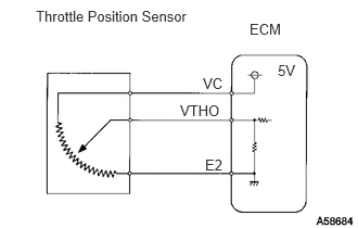
The throttle position sensor is mounted on the throttle body and detects the throttle valve opening angle.
When the throttle valve is fully closed, the sensor transmits a signal voltage of approximately 0.4 to 0.8 V to terminal VTHO of the ECM. This signal voltage increases in proportion to the opening angle of the throttle valve, reaching approximately 3.2 to 4.8 V when the throttle valve is fully open.
The ECM determines the vehicle driving conditions from these signals and uses this information in functions such as air-fuel ratio correction, power increase correction and fuel-cut control.
| DTC No. | Detection Item | DTC Detection Condition | Trouble Area | MIL | Memory |
|---|---|---|---|---|---|
| P0120 | Throttle / Pedal Position Sensor / Switch "A" Circuit | Open or short in throttle position sensor circuit for 0.5 seconds or more (1 trip detection logic) | ·
Open or short in throttle position sensor circuit ·
Throttle position sensor ·
ECM |
Comes on | DTC stored |
- HINT:
- ·
Fail-safe mode: When this DTC is set, the ECM enters fail-safe mode. During fail-safe mode, the ECM uses a constant value stored in the ECM memory as a throttle position sensor signal. Fail-safe mode continues until a pass condition is detected.
·When this DTC is set, check the throttle valve opening angle using the intelligent tester or Techstream. Enter the following menus: Powertrain / Engine / Data List / Throttle Position.
| Throttle Valve Fully Closed | Throttle Valve Fully Open | Trouble Area |
|---|---|---|
| 0% | 0% | VC circuit open
VTH circuit open or short |
| Approximately 100% | Approximately 100% | E2 circuit open |
- Powertrain > Engine > Data List
-
Tester Display Throttle Position - 50003 206 36
WIRING DIAGRAM
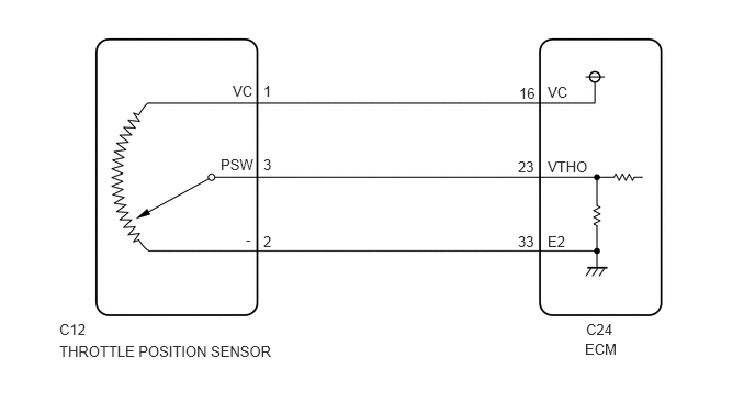
CAUTION / NOTICE / HINT
- HINT:
- ·
If other DTCs relating to different systems that have terminal E2 as the ground terminal are output simultaneously, terminal E2 may have an open circuit.
·Read freeze frame data using the intelligent tester or Techstream. Freeze frame data record the engine condition when malfunctions are detected. When troubleshooting, freeze frame data can help determine if the vehicle was moving or stationary, if the engine was warmed up or not, if the air-fuel ratio was lean or rich, and other data, from the time the malfunction occurred.
PROCEDURE
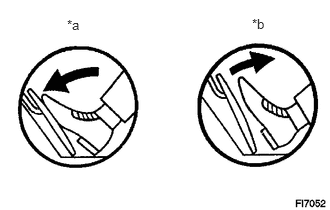
| *a | Depressed |
| *b | Released |
Connect the intelligent tester or Techstream to the DLC3.
Turn the ignition switch to ON.
Turn the intelligent tester or Techstream on.
Enter the following menus: Powertrain / Engine / Data List / Throttle Position.
- Powertrain > Engine > Data List
-
Tester Display Throttle Position - 50003 206 36
Read the value displayed on the intelligent tester or Techstream when the accelerator pedal is released and depressed.
- Result:
Accelerator Pedal Throttle Position (%) Proceed To Released → Depressed 0 (constant) A From approximately 0 to 75 B Approximately 100 (constant) C
A
B
C
Inspect the throttle position sensor.
Click hereEngine / Hybrid System>3SZ-VE ENGINE CONTROL>THROTTLE BODY>INSPECTION
- Result:
Proceed to OK NG
OK
NG
Disconnect the ECM connector.
Measure the resistance according to the value(s) in the table below.
- Standard Resistance:
Tester Connections Throttle Valve Condition Specified Conditions C24-16 (VC) - C24-33 (E2) - 2.5 to 5.0 kΩ C24-23 (VTHO) - C24-33 (E2) Fully closed 0.3 to 5.8 kΩ C24-23 (VTHO) - C24-33 (E2) Fully open 1.98 to 9.16 kΩ
- Standard Resistance (Check for Short):
Tester Connections Condition Specified Conditions C24-16 (VC) - Body ground Always 10 kΩ or higher C24-23 (VTHO) - Body ground Always 10 kΩ or higher
Reconnect the ECM connector.
- Result:
Result Proceed to NG A OK (for LHD) B OK (for RHD) C
A
B
C
Inspect the throttle position sensor.
Click hereEngine / Hybrid System>3SZ-VE ENGINE CONTROL>THROTTLE BODY>INSPECTION
- Result:
Proceed to OK NG
OK
NG
Disconnect the ECM connector.
Disconnect the throttle position sensor connector.
Measure the resistance according to the value(s) in the table below.
- Standard Resistance (Check for Open):
Tester Connections Condition Specified Conditions C12-1 (VC) - C24-16 (VC) Always Below 1 Ω C12-3 (PSW) - C24-23 (VTHO) Always Below 1 Ω C12-2 (-) - C24-33 (E2) Always Below 1 Ω
- Standard Resistance (Check for Short):
Tester Connections Condition Specified Conditions C12-1 (VC) or C24-16 (VC) - Body ground Always 10 kΩ or higher C12-3 (PSW) or C24-23 (VTHO) - Body ground Always 10 kΩ or higher
Reconnect the throttle position sensor connector.
Reconnect the ECM connector.
- Result:
Result Proceed to NG A OK (for LHD) B OK (for RHD) C
A
B
C